
2.6.2. Operating the Robot
This section covers the essential tasks for operating the robot, including managing programs, configuring tools, handling inputs and outputs, and controlling robot movements.
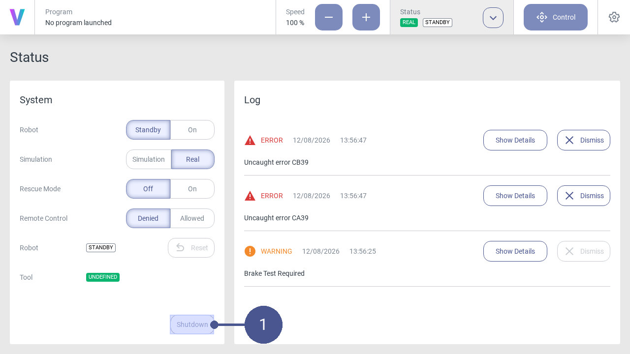
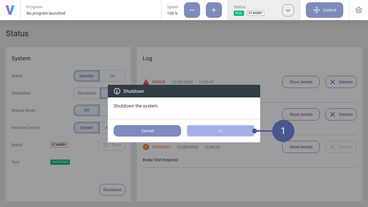
Switch off the voraus.core
The voraus.core can be switched off in the user interface.
Manage Programs
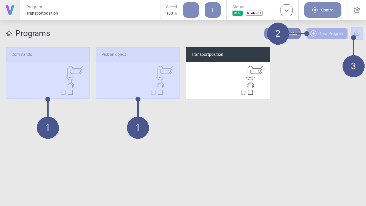
Programs (Fig. 69/➊) are displayed on the home screen of the user interface.
A new program can be created via the New Program button (Fig. 69/➋). Programs can be imported via the Import Program button (Fig. 69/➌).
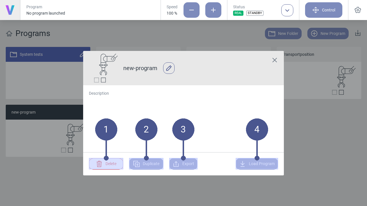
To manage existing programs, click on the desired program on the main screen.
Note
The menu (Fig. 70) opens.
Click on one of the following buttons:
Fig. 70/➋ |
Delete - Delete the selected program. |
Fig. 70/➋ |
Duplicate - Copy the selected program. |
Fig. 70/➌ |
Export - Export the selected program. |
Fig. 70/➍ |
Load Program - Load the selected program. |
Folders
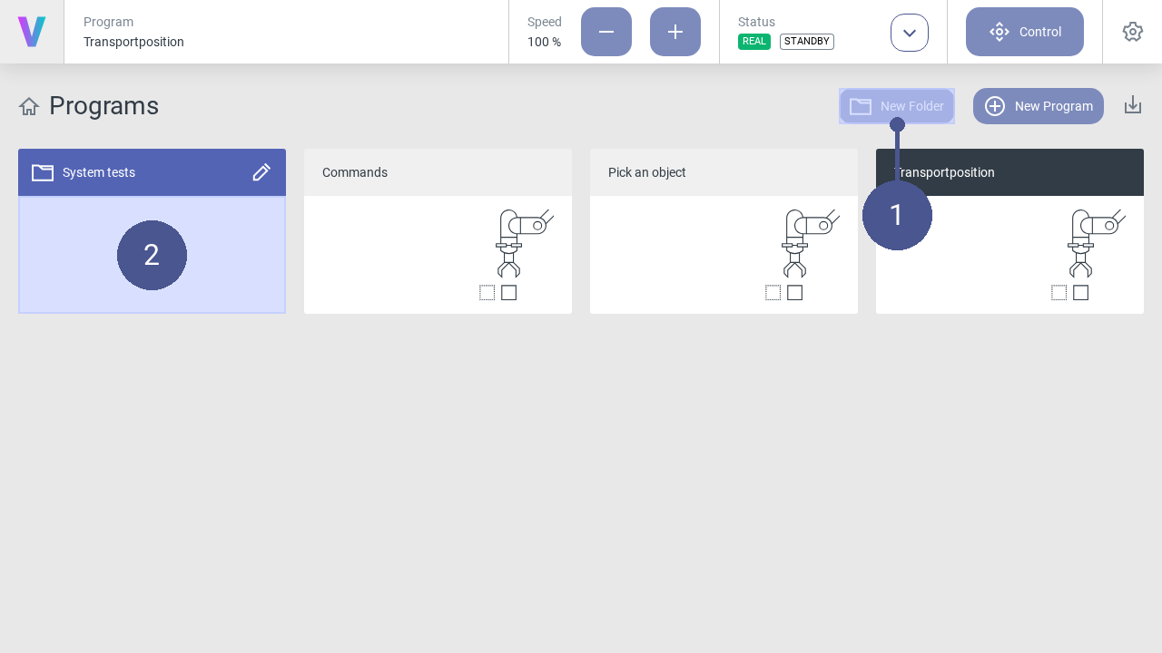
Folders can be created on the home screen in addition to programs. They are useful for grouping and sorting programs.
To create a new folder:
Press the New Folder button (Fig. 71/➊).
Enter a meaningful name.
Press the save icon.
Programs can be moved to folders (Fig. 71/➋) via drag and drop. To move a program out of a folder, it must be dragged and dropped onto the navigation title Programs.
It is possible to rename and delete folders by clicking the edit icon. Please note deleting a folder deletes all included programs too. This cannot be undone. Folder cannot be deleted when an included program is currently loaded.
Use Simulation Mode
Note
The functionality of the simulation mode is available when using voraus.core with a KUKA or Yaskawa robot. It is not supported for a virtual environment or with FANUC robots.
In simulation mode, robot movements are simulated in the user interface, based on a virtual robot model. The real robot does not perform any movements in simulation mode.
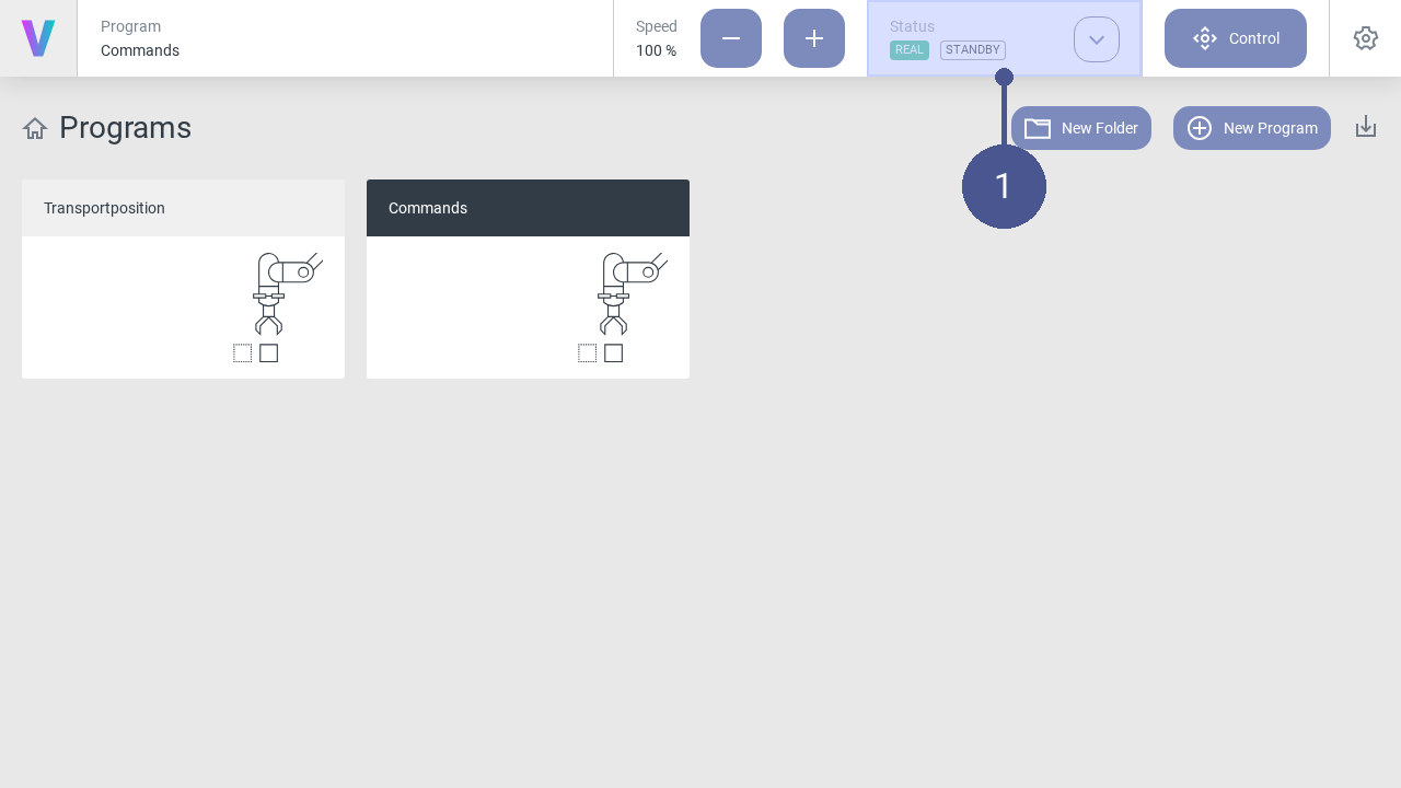
Click on the Status button on the home screen (Fig. 72/➊).
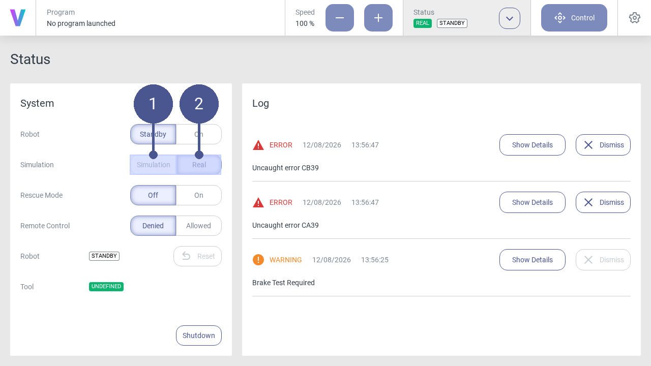
To activate the simulation mode, click on the Simulation button in the status menu. (Fig. 73/➊).
The simulation mode is activated.
All robot movements (e.g., when executing programs or when moving manually) are now displayed exclusively virtually based on the robot model in the user interface.
3. To deactivate the simulation mode, click on the Real button in the status menu. (Fig. 73/➋).
Configure Tool
Click on the Status button on the home screen (Fig. 74/➊).
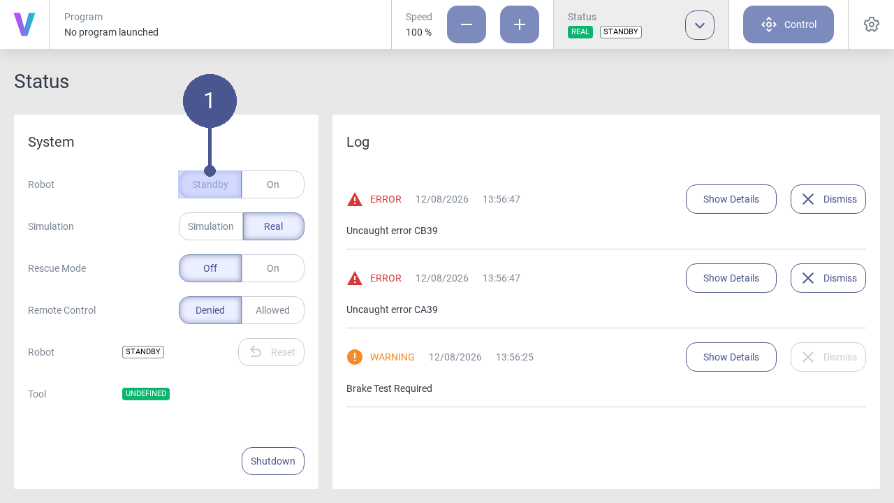
Click Standby in the status menu. (Fig. 75/➊).
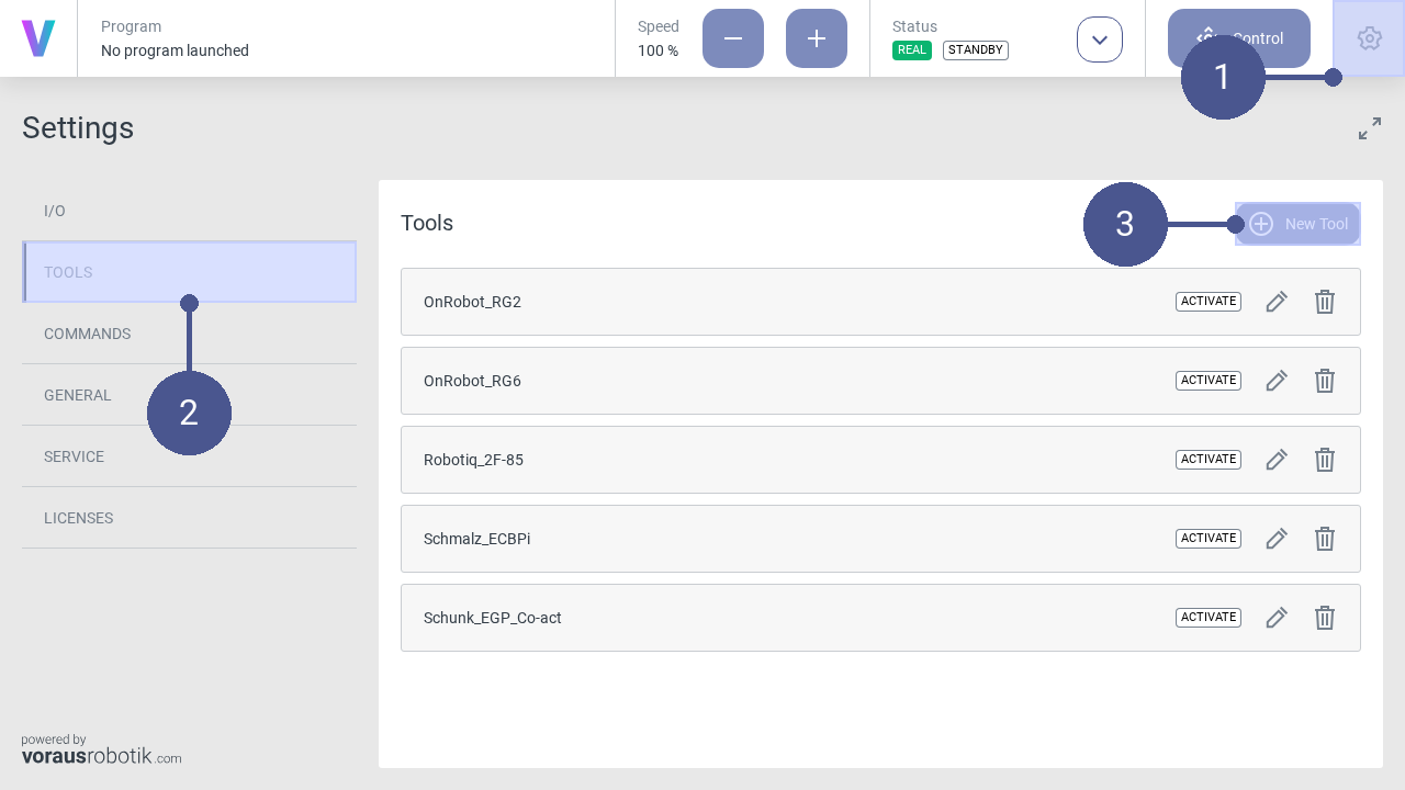
Click the settings icon in the navigation bar (Fig. 76/➊), to open the settings menu.
In the settings menu, click on TOOLS in the left tab to open the window of the tool’s settings (Fig. 76/➋).
Click on New Tool (Fig. 76/➌).
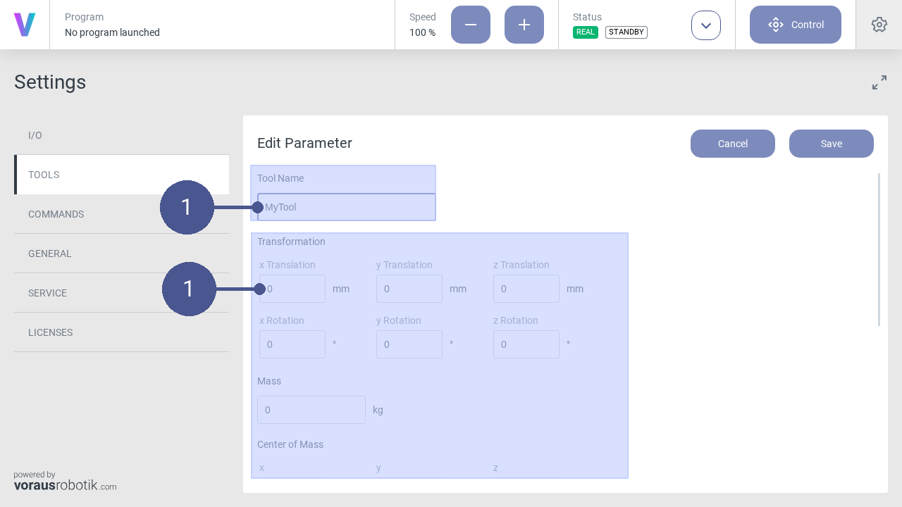
Name the tool and enter its parameters (Fig. 77/➊).
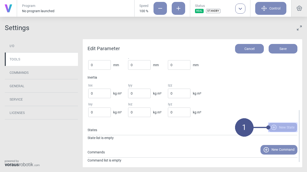
Click New State to open the state menu (Fig. 78/➊).
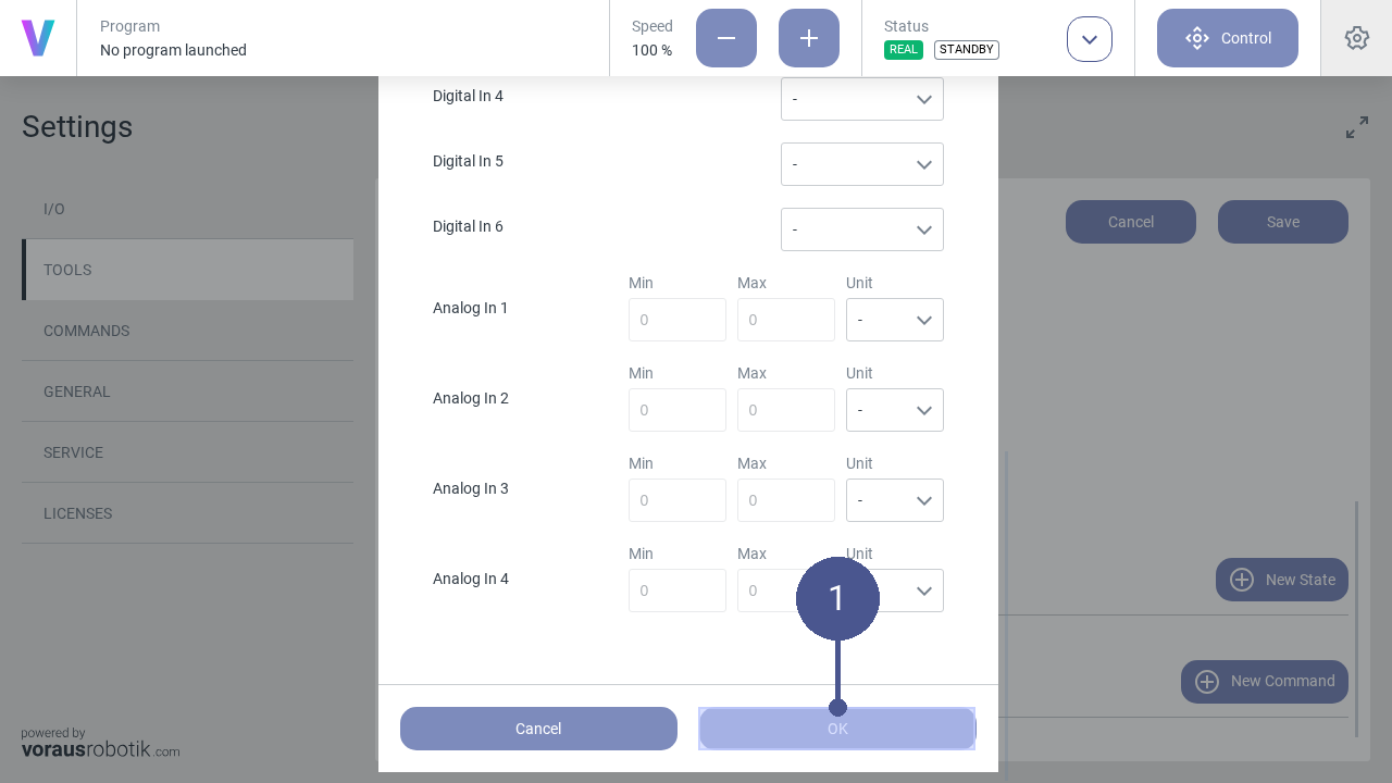
8. In the state menu, define the states of the digital outputs and the digital inputs according to the operator’s specifications and confirm with OK (Fig. 79/➊).
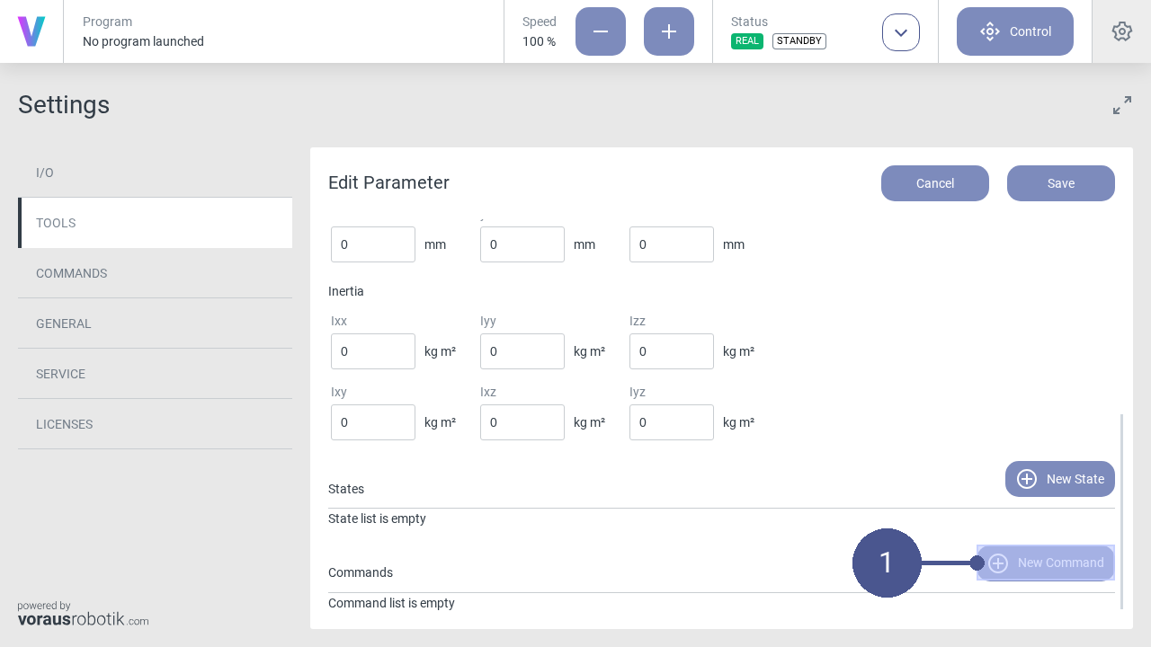
Click New Command to open the command menu (Fig. 80/➊).
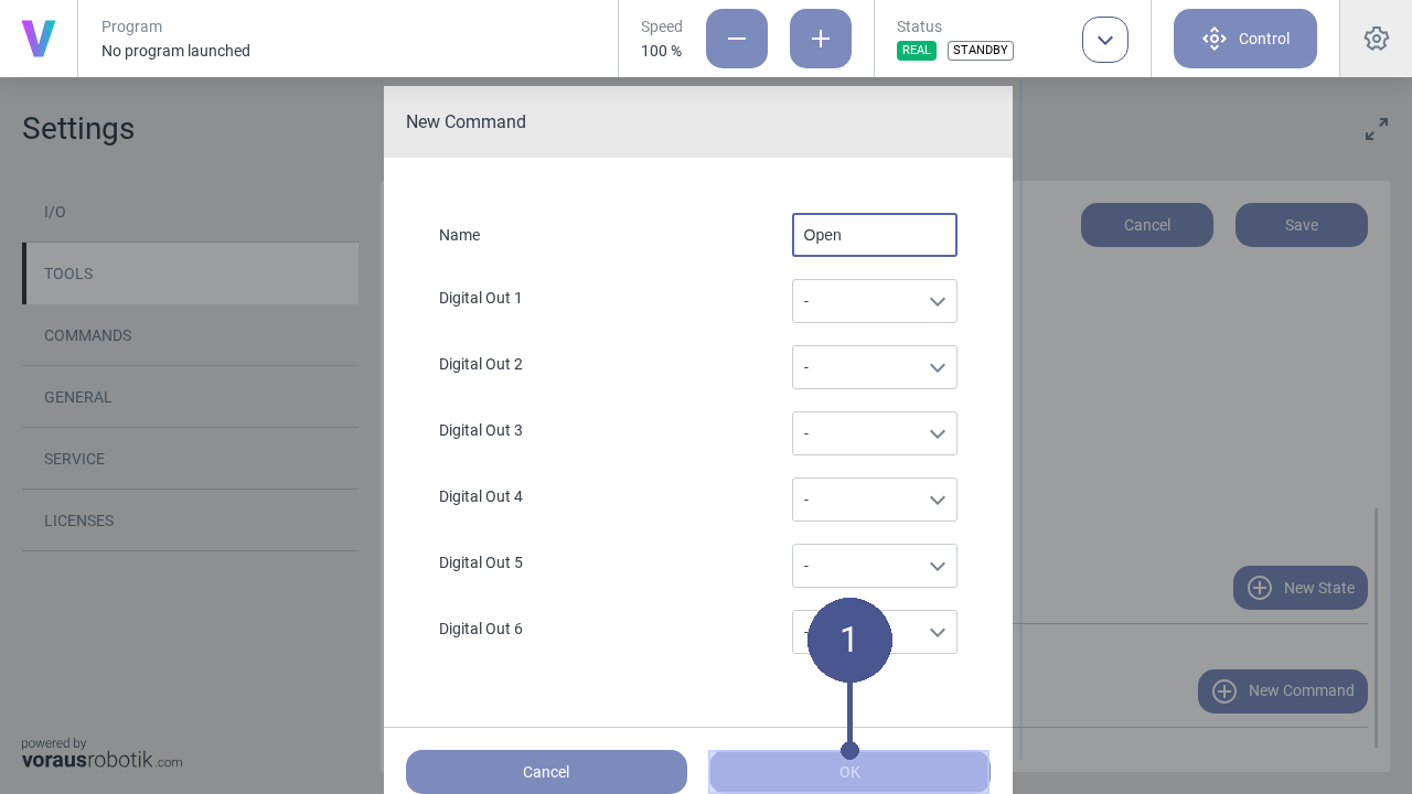
In the command menu, define the states of the digital outputs according to the operator’s specifications and confirm with OK (Fig. 81/➊).
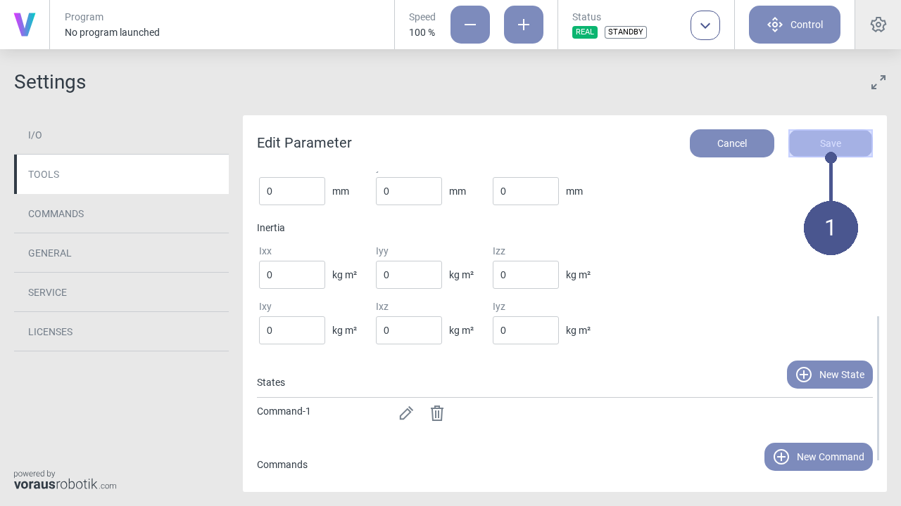
Click Save to save the tool parameters (Fig. 82/➊).
Click on the Status button on the home screen (Fig. 83/➊).
Click Standby in the status menu. (Fig. 84/➊).
Click the settings icon in the navigation bar (Fig. 85/➊), to open the settings menu.
In the settings menu, click on TOOLS in the left tab to open the window of the tool’s settings (Fig. 85/➋).
Click on New Tool (Fig. 85/➌).
Name the tool and enter its parameters (Fig. 86/➊).
Click Save to save the tool parameters (Fig. 87/➊).
Note
The Fig. 87 may show additional options that are not available in the voraus.core configuration with a KUKA robot.
Note
When configuring a tool with a KUKA robot, the tool information is not fully synchronized between the voraus.core and the robot controller. In particular, Cartesian poses reported by the voraus.core and the robot controller can refer to different reference coordinate systems. See Tool Configuration for details.
Click on the Status button on the home screen (Fig. 88/➊).
Click Standby in the status menu. (Fig. 89/➊).
Click the settings icon in the navigation bar (Fig. 90/➊), to open the settings menu.
In the settings menu, click on TOOLS in the left tab to open the window of the tool’s settings (Fig. 90/➋).
Click on New Tool (Fig. 90/➌).
Name the tool and enter its parameters (Fig. 91/➊).
Click Save to save the tool parameters (Fig. 92/➊).
Note
The Fig. 92 may show additional options that are not available in the voraus.core configuration with a Yaskawa robot.
Note
When configuring a tool with a Yaskawa robot, the tool information is not synchronized between the voraus.core and the robot controller. In particular, Cartesian poses reported by the voraus.core and the robot controller can refer to different reference tool coordinate systems. See Tool Configuration for details.
Warning
For Yaskawa robots, the tool’s mass properties cannot be transmitted to the robot controller. Therefore, its mass properties must be configured identically and directly in the Yaskawa robot controller in addition to the configuration in the voraus.core. Otherwise, the robot controller’s internal functions, such as dynamic model calculations and load monitoring, operate with incorrect load information.
Configure Digital Inputs & Outputs
Note
Configuring digital inputs and outputs is available only when using voraus.core in a virtual environment or with FANUC robots. It is not supported for KUKA robots.
The digital inputs and outputs are located within the I/O section in the settings menu Fig. 93. On the I/O page, all inputs (In) and outputs (Out) are displayed.
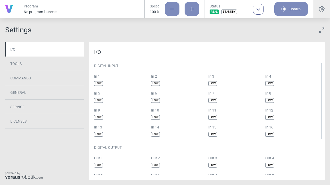
The status of each digital I/O channel can be in one of two states:
LOW: The I/O signal is at a low voltage level, typically representing an off or inactive state.
HIGH: The I/O signal is at a high voltage level, typically indicating an on or active state.
Digital Inputs
Digital inputs are used to receive signals from external devices or sensors. These inputs are essential for capturing data from your environment or interacting with other equipment like for example conveyor belts or light barriers.
Digital Outputs
Digital outputs are used to control external devices or machines, allowing the voraus.core to trigger actions in response to its programmed tasks. Digital outputs can be configured in multiple ways:
Clicking on the status badge of a digital output on the I/O page, to toggle the value manually. By clicking the badge a popup will open to double-check if you really want to change the value. Press OK to submit or press Cancel to discard the action.
Set one or multiple digital outputs in a program by using the Set Digital Outputs command.
Safety Precautions
When configuring digital inputs and outputs, ensure that all safety guidelines and protocols are followed. Incorrect I/O settings can lead to unintended actions or hazards. Always conduct thorough testing and verification to guarantee the robot’s safe operation.
Camera Settings
Note
Camera settings are available only when using voraus.core in a virtual environment. They are not supported for KUKA, Yaskawa, or FANUC robots.
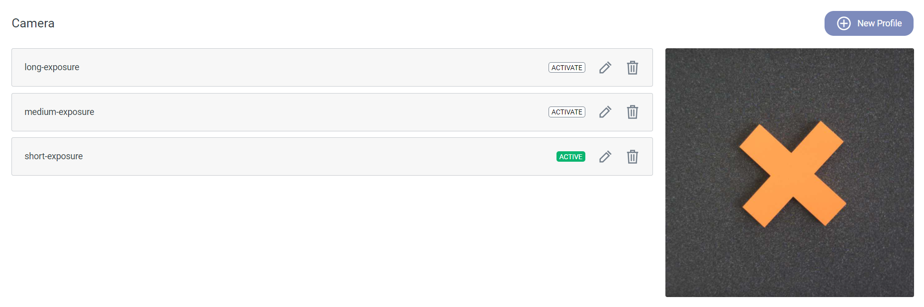
Description
Depending on the lighting conditions of the environment and the contrast between any objects and the background, it can
be beneficial to tweak the camera settings. You can edit the default camera settings and define new ones within the
settings menu. To access it, click the settings icon  in the top right corner of the HMI and select
the CAMERA section. All available camera setting profiles are listed in this menu. To create a new profile, press
the New Profile button on the right (see Fig. 94). To edit or delete
existing profiles, click the edit icon
in the top right corner of the HMI and select
the CAMERA section. All available camera setting profiles are listed in this menu. To create a new profile, press
the New Profile button on the right (see Fig. 94). To edit or delete
existing profiles, click the edit icon  respectively the delete icon
  next to the profile name. By
clicking the ACTIVATE badge you can switch between the defined profiles.
next to the profile name. By
clicking the ACTIVATE badge you can switch between the defined profiles.
Parameterization
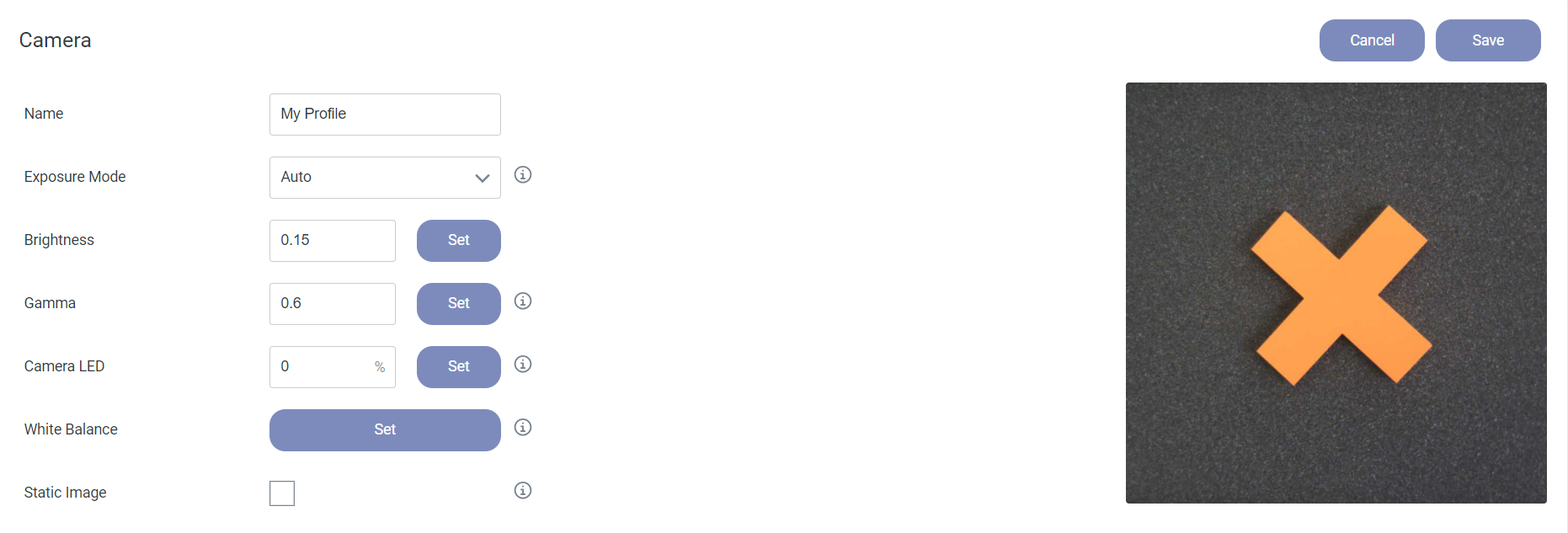
Name: Enter a name for the profile.
Exposure Mode: Choose between Manual and Auto.
Auto: The exposure time is chosen automatically. You can adjust the overall brightness of the camera frame by editing the Brightness value. The brightness factor can be set to any value in the range from 0.1 to 1.0.
Manual: You can set the Exposure Time [µs] value manually. The valid range is 10 µs to 40.000 µs.
Gamma: Value for the gamma correction of the incoming camera frames. Higher values let the image appear brighter, lower values darker. The valid range is from 0.25 to 2.0.
Camera LED: Percentage of the LED brightness between 0 and 100. 0 means the LEDs are switched off.
White Balance: The Set button adjusts the white balance. For this the camera has to be targeted at a white surface. The white balance is used to eliminate tint and improve the accuracy of the color representation.
Static Image: If checked the execution of the vision command inside a program is delayed until no more movement is detected in the camera frame.
Save: Save the current camera settings.
Cancel: Discard any changes.
Values of the Default Settings
Exposure Mode |
Auto |
Brightness |
|
Gamma |
0.6 |
Camera LED |
0 |
Static Image |
Off |
Additional Information
By deleting all camera profiles, the three default settings short/medium/long-exposure are restored automatically.
The Static Image option can be useful in applications with high robot velocities.
Create a New Program
The robot must be in manual operating mode.
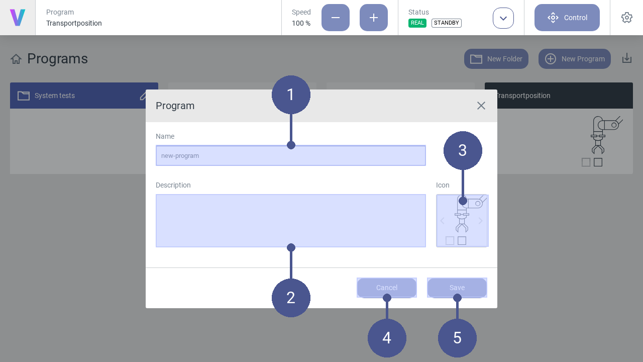
To create a new program, click New Program on the main screen. The menu (Fig. 96) opens.
Enter Name and Description of the program function (Fig. 96/➊ + ➋).
Select an appropriate Icon by using the arrows (Fig. 96/➌).
Click Save to create the program (Fig. 96/➎). Otherwise click Cancel to return to the main screen (Fig. 96/➍).
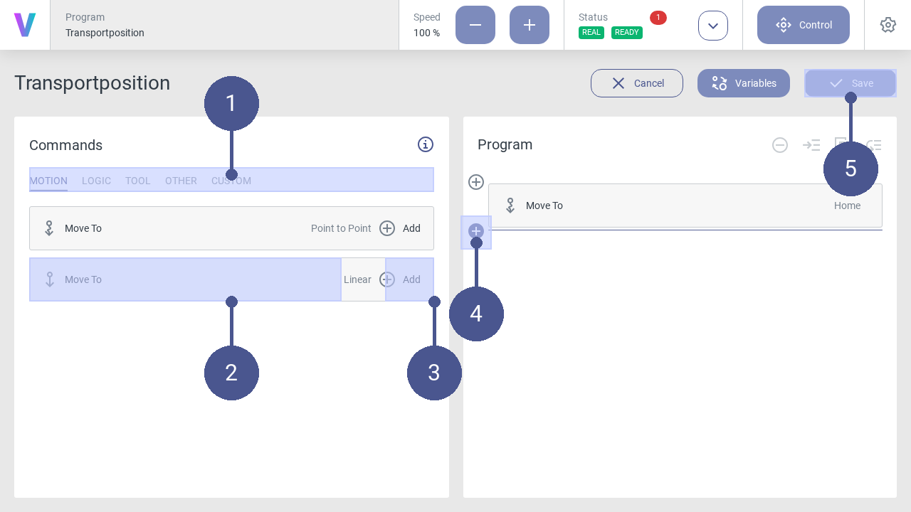
5. In the program menu (right half of the screen), define the program sequence by inserting individual command blocks (Fig. 97).
To do so, proceed as follows:
6. In the tab select the required command category by clicking on it (Fig. 97/➊). The following command categories are available:
MOTION
Define movement patterns of the robot.
VISION
This functionality is only available for the voraus.core in a virtual environment.
Use the camera on the media flange, e.g., for object detection.
LOGIC
Select logic commands such as repeat, to execute a group of commands in a loop.
TOOL
This functionality is only available for the voraus.core in a virtual environment.
Control the selected tool.
OTHER
Create a group of commands to improve the program’s readability.
CUSTOM
Apply your individual commands.
Select the desired command block (Fig. 97/➋) and add it to the program sequence by clicking on the plus symbol (Fig. 97/➌) The new command block is added to the program flow at the position of the colored cursor (Fig. 97/➍).
After assigning all the required command blocks, Save your final program and enjoy its impact (Fig. 97/➎).
The newly created program can be loaded and executed by the operator on the main screen.
Load and Execute Programs
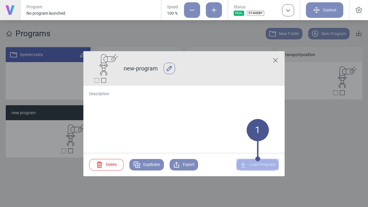
To load a program, click on the button of the desired program on the home screen.
Note
The pop-up (Fig. 98) opens.
2. Click the Load Program button to open the selected program (Fig. 98/➊).
In the program menu (Fig. 99), the program sequence is displayed as a sequence of the individual command blocks (Fig. 99/➋).
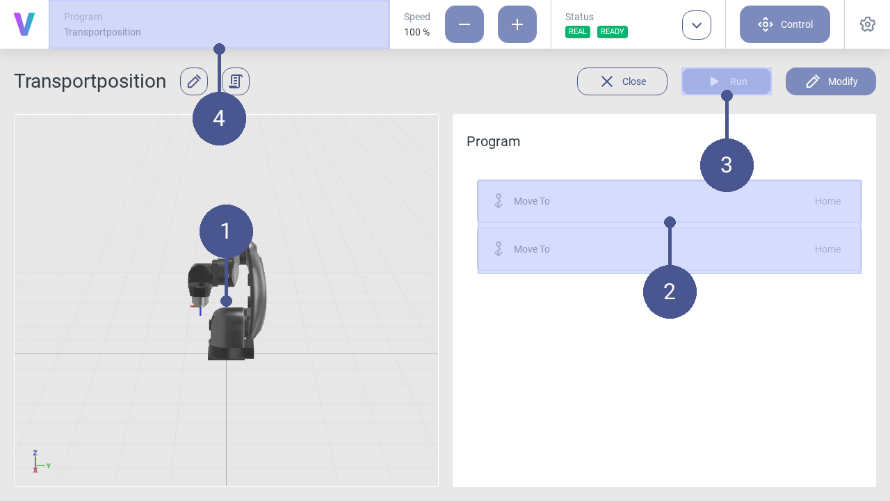
To start the program, click Run (Fig. 99/➌).
The robot executes the program according to the sequence of the command blocks.
Note
Virtual robot
In the left menu section, the movements are displayed using a virtual robot model (Fig. 99/➊). In the navigation bar, the currently loaded program is displayed at any time (Fig. 99/➍).
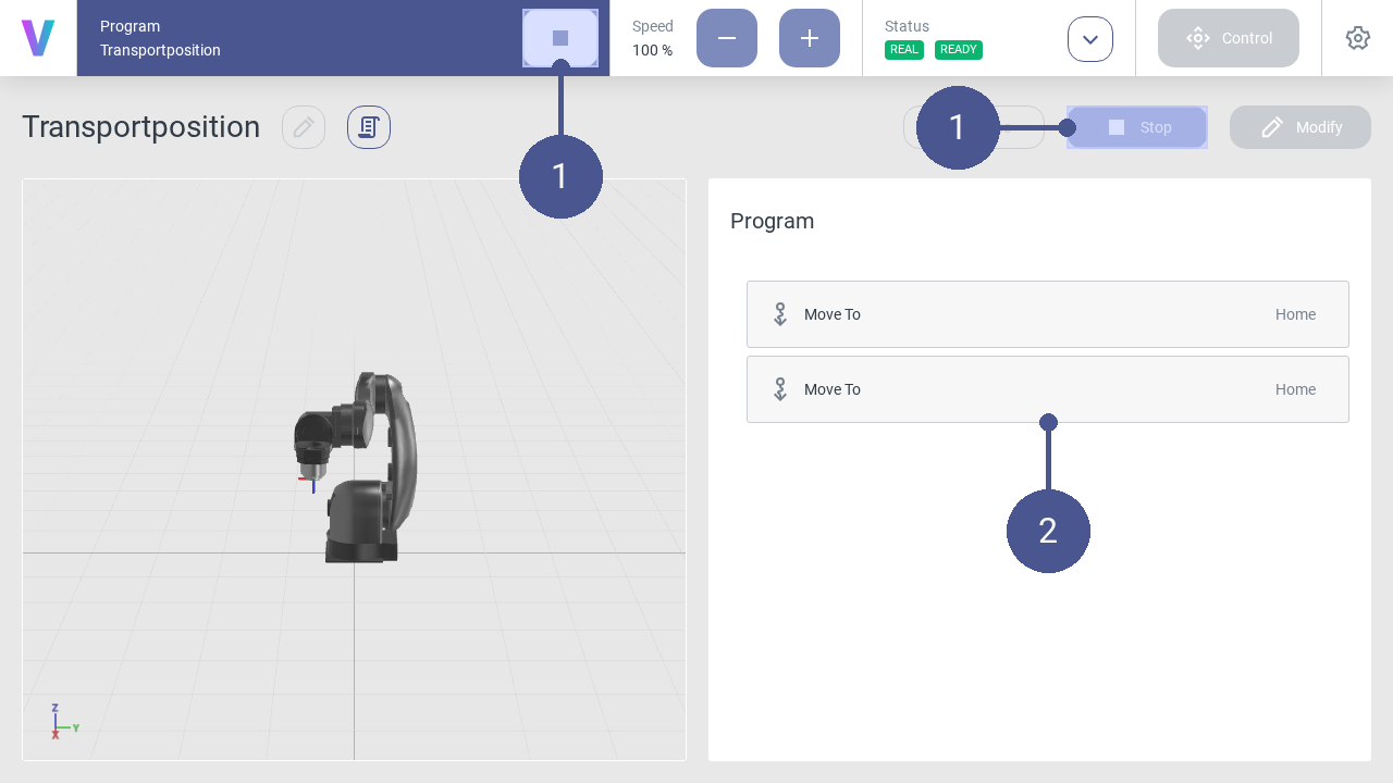
To stop the program, click the Stop button in the navigation bar or the program menu (Fig. 100/➊).
Note
Program sequence
The currently executed command sequence is displayed via a colored time bar (Fig. 100/➋).
Edit Program
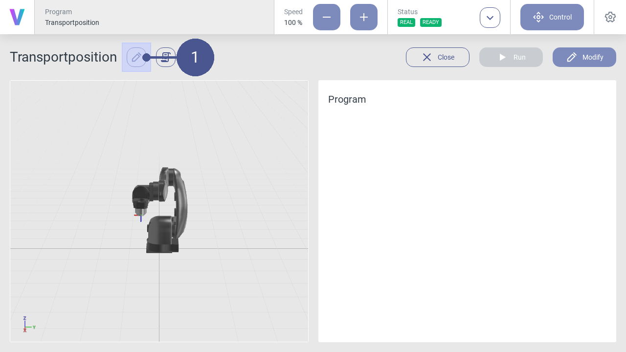
To edit a program, click on the pencil icon next to the program name (Fig. 101/➊).
Enter a new name or change the program description if needed.
Note
The pop-up menu opens (Fig. 102).
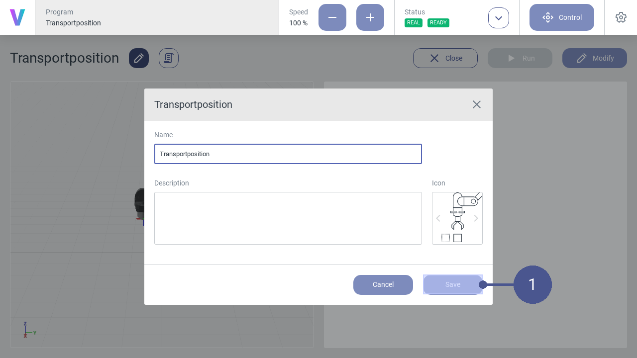
Click Save to save the changes (Fig. 102/➊).
Note
The program can also be edited by clicking on the icon next to the program name in the pop-up window within the home screen.
Move Robot Manually
Warning
Risk of injury due to manual movement of the real robot!
When moving the robot manually, there is a possibility that the robot is moved in an unsafe environment without prior risk assessment. In the event of physical contact, injuries may occur due to improper manual operation of the robot.
Ensure that the robot is only moved manually by the responsible system integrator.
Ensure that no unauthorized persons are in the working and danger area of the robot.
Ensure that no pointed or sharp-edged tools or devices are mounted to the robot.
The robot must be in manual operating mode.
The FANUC robot must be in automatic mode. The steps are described in section Switch to automatic mode.
The KUKA robot can be in manual or automatic mode.
The Yaskawa robot can be in automatic/play mode.
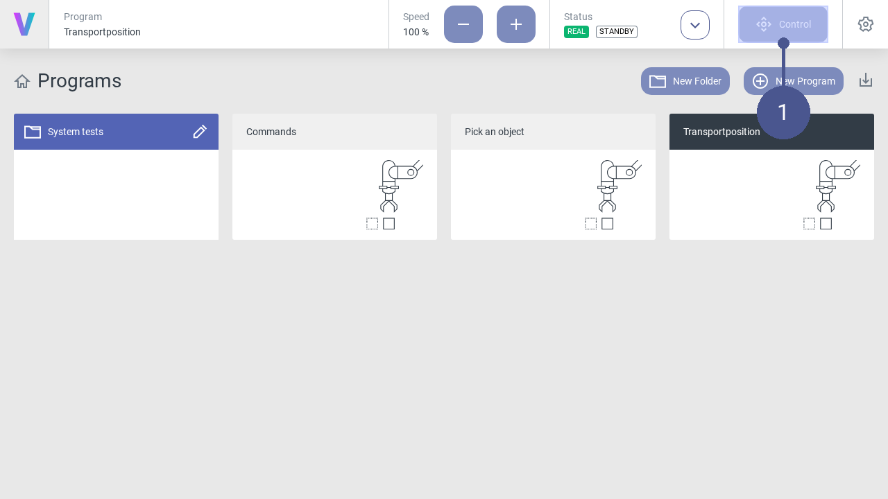
Click Control in the navigation bar (Fig. 103/➊).
Note
The control menu opens (Fig. 104).
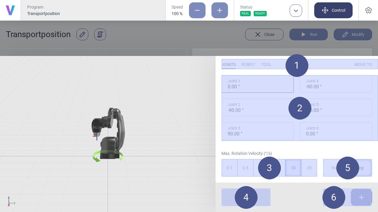
Select the desired coordinate system from the tabs (Fig. 104/➊).
Select the axis for which a movement is to be executed (Fig. 104/➋).
Select the jogging method (Fig. 104/➎):
- Step (Step-Jogging)
The robot moves step by step along the selected axis.
- Jog (Jogging)
The robot moves continuously along the selected axis.
Select angle length and angular velocity (Fig. 104/➌).
Click the plus or minus button to move the robot forward or backward along the selected axis (Fig. 104/➏).
Note
Move robot
Press and hold the plus or minus button to move the robot in a continuous motion while jogging.
Move robot to input pose
The robot can be manually moved to a specific target pose. Therefore, the target pose needs to be entered into the input fields.
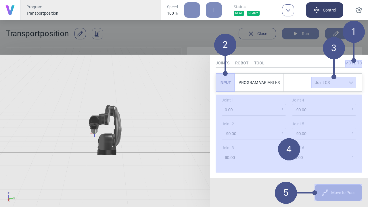
Open the control panel.
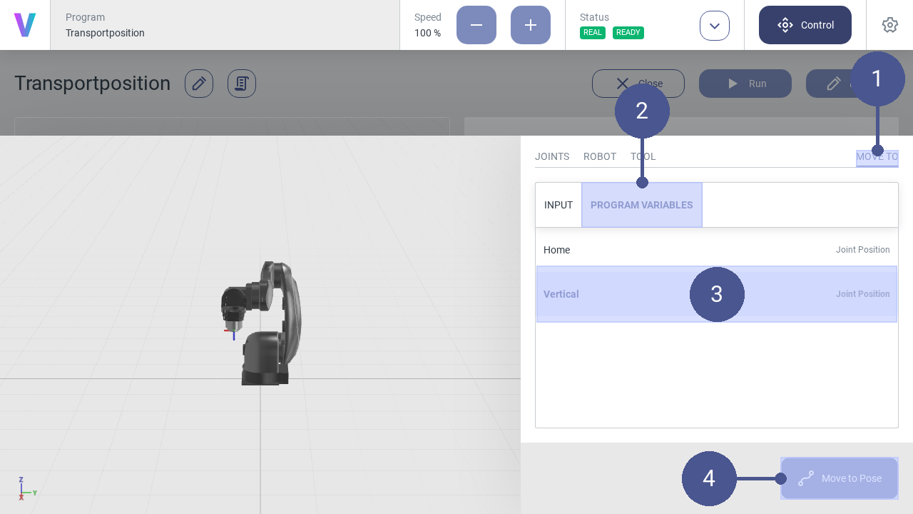
Navigate to MOVE TO (Fig. 105/➊) and select INPUT (Fig. 105/➋).
Select the coordinate system of the target pose (Fig. 105/➌).
Enter the target pose in the input fields (Fig. 105/➍).
Press and hold the Move to Pose button until the target pose is reached (Fig. 105/➎).
The robot is now at the target pose.
Move robot to program variable
The robot can be manually moved to a specific program pose variable. Therefor, the program variable needs to be selected first.
Reset System After Software Failure
The following section describes how to restart the robot after an emergency stop or after a change of the operating state.
Reset software failures
A software error can, for example, be triggered by system errors or incorrect movement of the robot.
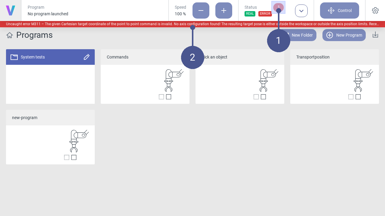
When a system error is triggered, a notification appears in the status bar (Fig. 107/➊) and the error message is displayed in the notification bar (Fig. 107/➋).
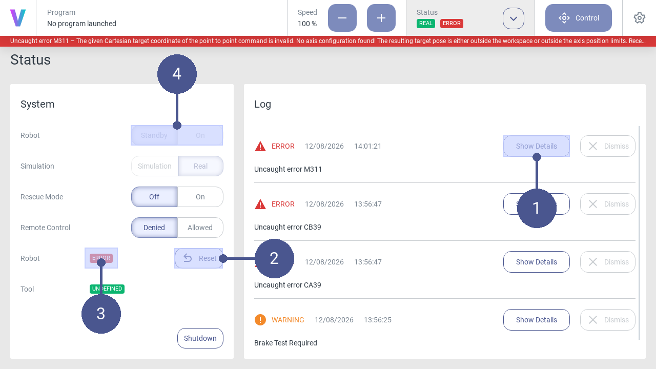
Open the status page and view details of the error message in the log (Fig. 108/➊).
Click Reset (Fig. 108/➋). The robot is set back to the Standby status (Fig. 108/➌). This can take a few seconds.
The robot can then be switched on again (Fig. 108/➍).
Other errors may be triggered during the process. In this case, follow the instructions in the log.
Create a Move to Command
A new program has been created.
After creating a new program, the program editor opens automatically. Logic can be added to the program by adding individual commands via drag and drop or by clicking.

Click the Add button of the Move to - Point to Point command in the program menu to open the window for a new motion command (Fig. 109/➊).
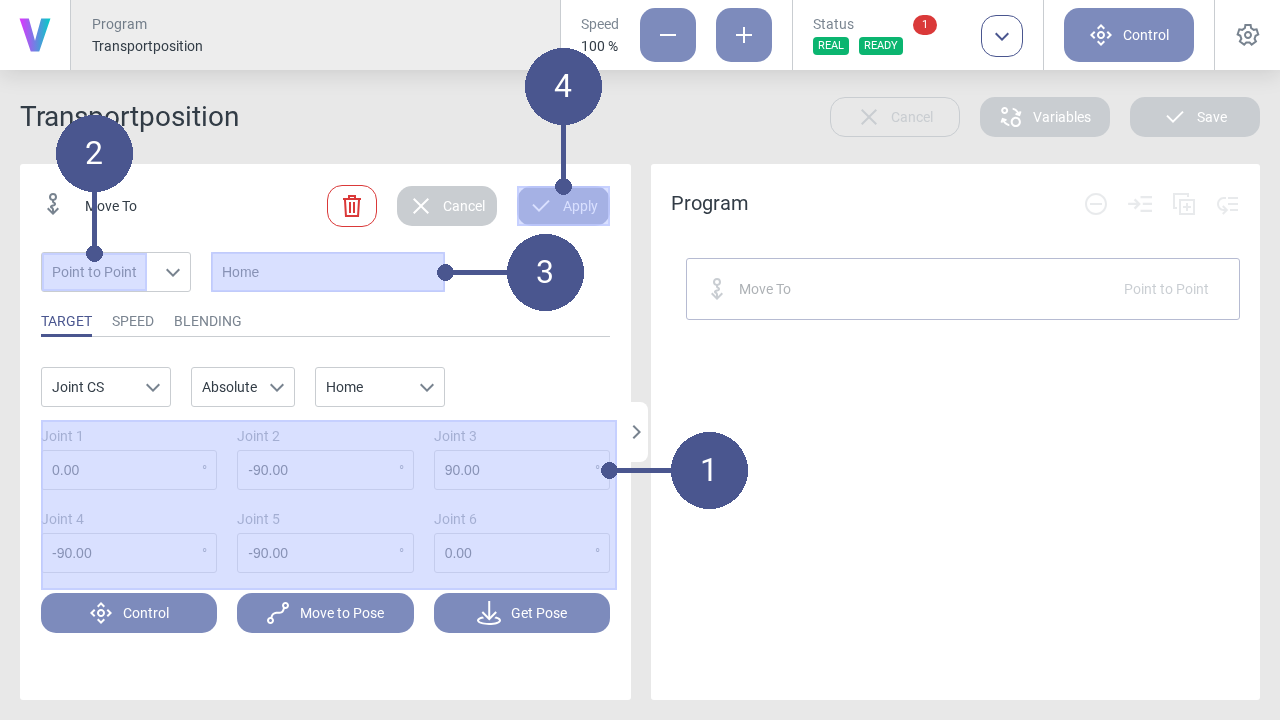
Parameterize the motion command for the home position according to the values (Fig. 110/➊).
Make sure that the Point to Point entry is selected in the drop-down list (Fig. 110/➋). Individual adjustments are possible in the tabs.
Enter the name of the motion command (e.g., Home) (Fig. 110/➌).
Save the command with Apply (Fig. 110/➍).
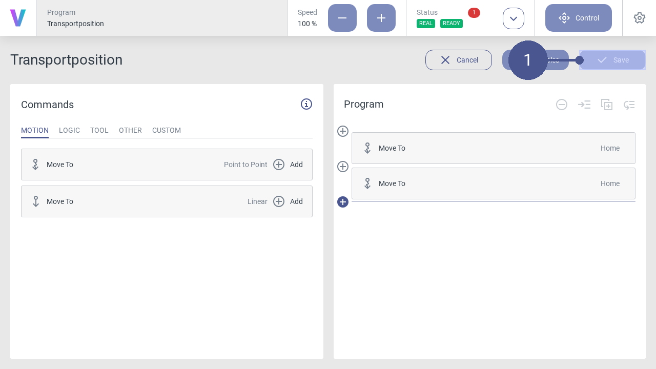
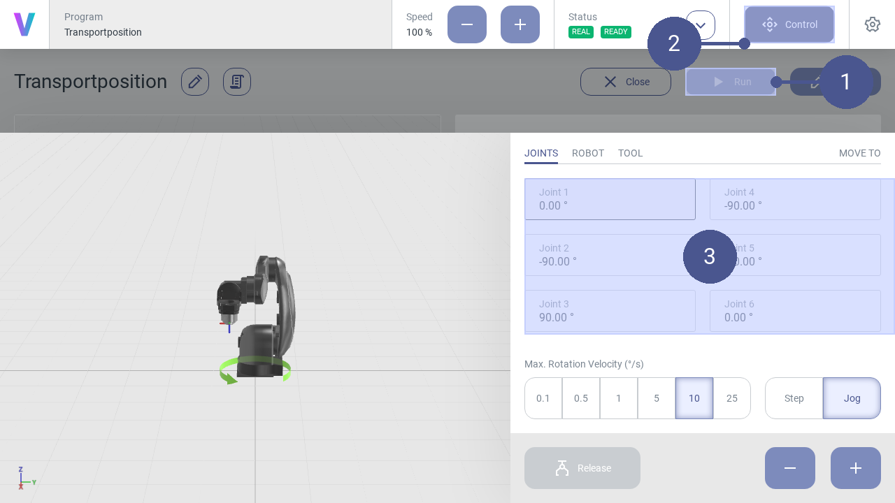
When your program is final, click on the Save button (Fig. 111/➊).
The new program can be loaded and executed in the overview screen. Before running your program on a real robot, it’s possible to simulate your path with the digital twin first. To check and switch the mode, have a look on the status screen. While running the program a digital twin of the robot is shown.
Create variable of robot pose
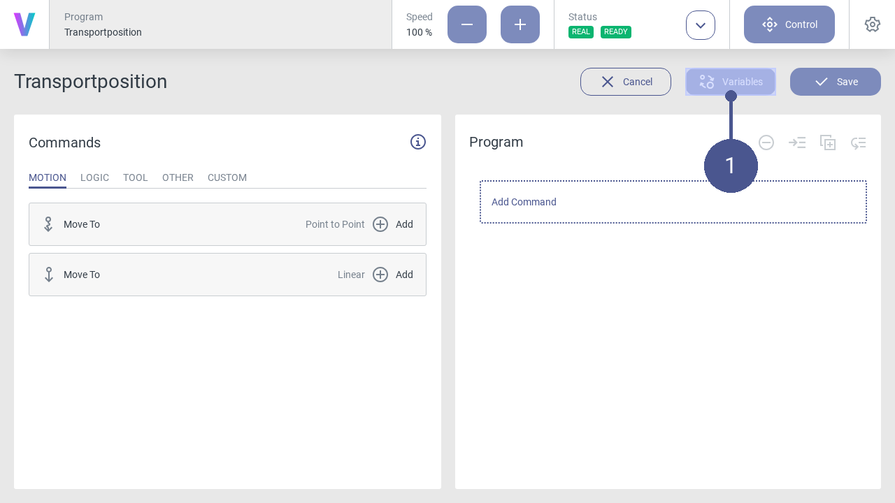
Click the Variables button in the program menu to open the window for managing and creating variables (Fig. 112/➊).
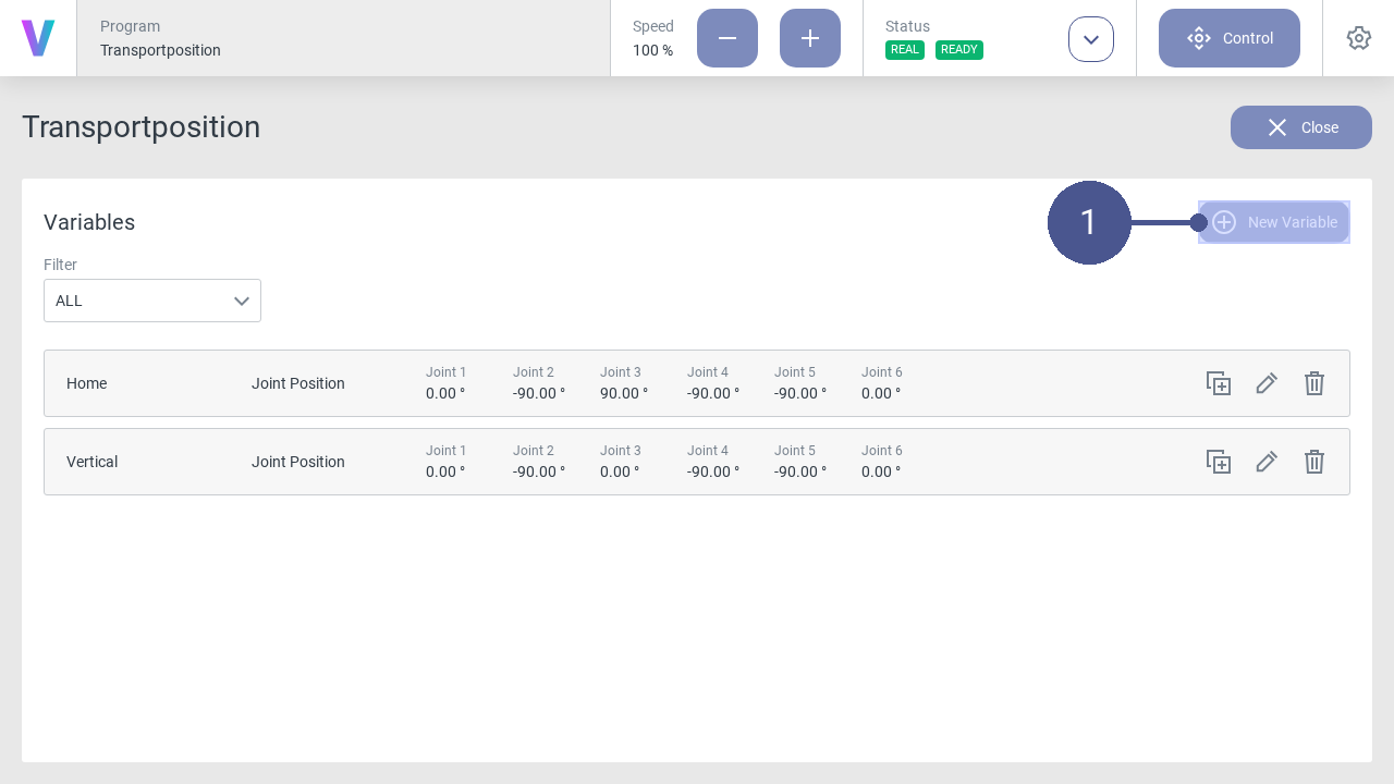
On the variables page, click the New Variable button to create a new variable (Fig. 113/➊).
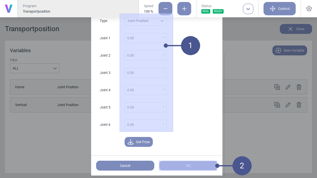
Select the Type Joint Position and parameterize the variable for the position (Fig. 114/➊).
Enter the name of the variable (e.g., Home).
Save the variable with OK (Fig. 114/➋)
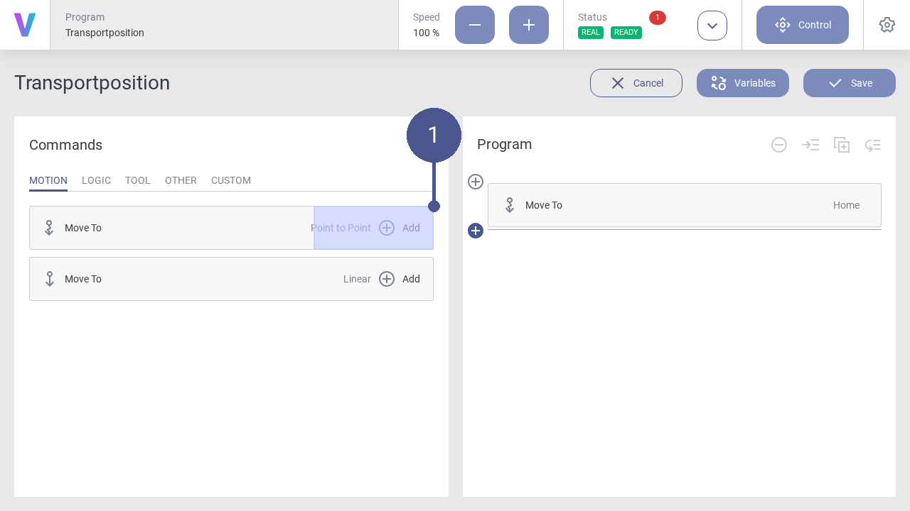
Click on the Add button in the program menu to open the window for an additional motion command with the created variable (Fig. 115/➊).
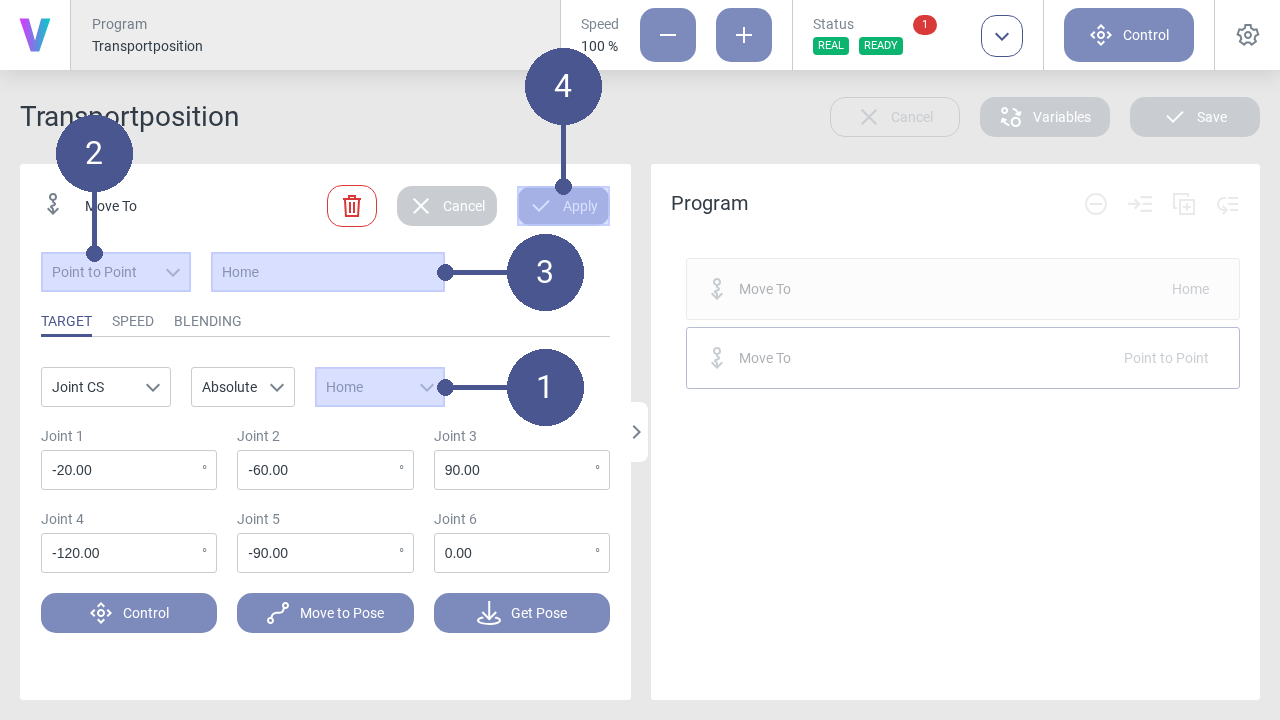
Use the drop-down list to select the variable Home (Fig. 116/➊). Afterwards the coordinates appear in the fields of the axes.
Make sure that the Point to Point entry is selected in the drop-down list (Fig. 116/➋).
Enter the name of the movement command (Fig. 116/➌).
Save movement command with Apply (Fig. 116/➍).
Click on the Save button (Fig. 117/➊).
Verify Position
Note
Position verification is available only when using voraus.core in a virtual environment. It is not supported for KUKA, Yaskawa, or FANUC robots.
If the robot has not been switched off properly (e.g., power supply to the robot controller has been interrupted), the reference position may be lost. In this case, the current position of the robot must be verified at the next restart. The pop-up window for position verification is automatically displayed in the user interface.
Requirements
The robot is in the manual operating mode.
No program is executed.
Activate Remote Control
Note
The functionality of activating remote control is available only when using voraus.core in a virtual environment or with FANUC robots. It is not supported for KUKA robots.
This chapter describes the activation of the remote control interface (OPC UA) via the operator.
For examples of how to use the external OPC UA server in an application, see chapter Using the External OPC UA Server
Note
The external OPC UA server can be reached via the robot’s IP address <IP-to-running-voraus.core> with the port 4840.
Warning
Risk of injury due to unexpected robot movement in remote mode!
When remote mode is active, the robot can be operated via an external remote control, e.g., a PLC or a Python client. This means that a single point of control is no longer guaranteed and there is a possibility that robot movements are commanded from an external source (by people or machines). Before activating the remote mode, ensure:
The system integrator has identified the risks arising from remote access and taken them into account in his risk assessment of the robot application.
The system integrator has taken appropriate measures to minimize the risks.
The system integrator has actively approved remote access.
There is no person in the danger zone of the robot.
Functions in remote mode
The following robot functions are available in remote mode:
Start programs.
Stop programs.
Perform a reset of the robot.
Set digital outputs.
Read and set program variables
Requirements
The following requirements must be met before remote mode can be activated:
No person is in the danger zone of the robot.
Remote mode is approved by the system integrator.
The robot is in the manual operating mode.
No program is being executed.
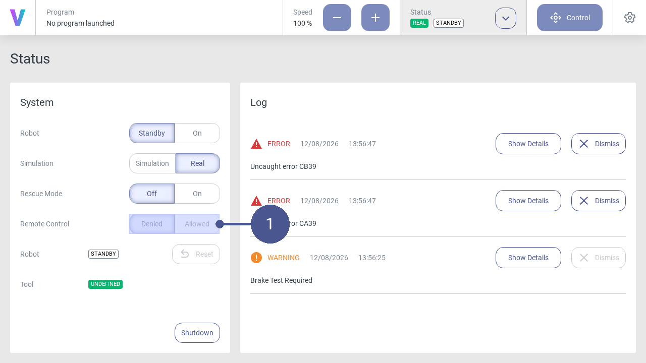
Click on the Allowed button in the Remote control item in the status menu (Fig. 119/➊).
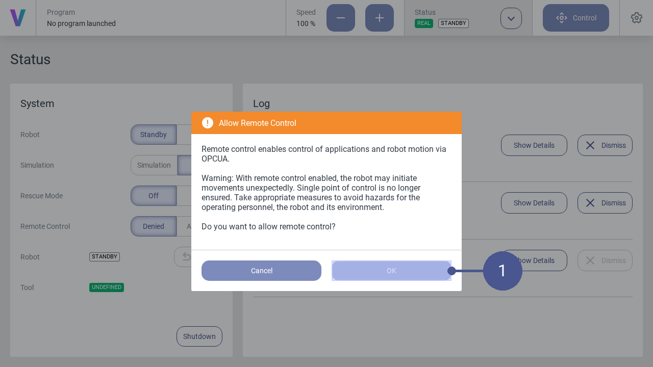
Confirm with OK to activate the remote mode (Fig. 120/➊).
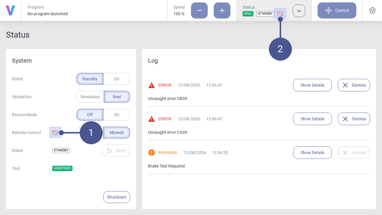
When the remote mode is active, the following icons are displayed in the user interface: