Roboception - Hand-Eye-Calibration
This command can be used calibrate the robot to camera transformation for your system. The command is the link between the robot interface and the Roboception camera, handling the calculation and conversion of poses. The Roboception supports both Eye-In-Hand, where the camera is mounted to the end-effector of the robot, and Hand-In-Eye calibrations where the camera is statically mounted and looks at the end-effector of the robot. For a detailed tutorial on the calibration process, please refer to the Roboception Hand-eye calibration documentation.
Warning
The current version of the voraus.app //Roboception only supports a statically mounted camera. Cameras mounted to the robot are not supported yet.
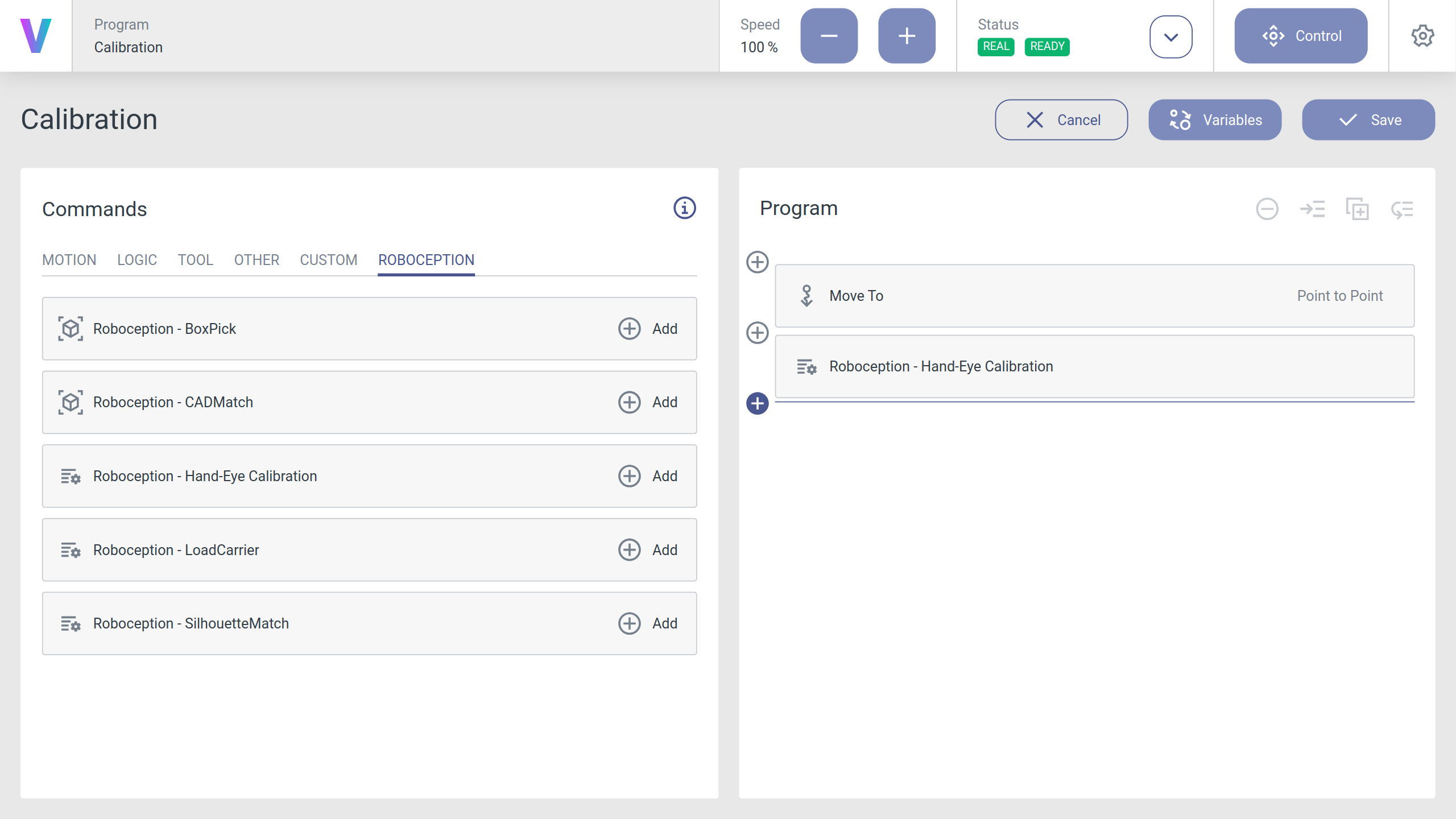
It is recommended to create a new program for the Hand-eye calibration and to insert the Roboception - Hand-Eye-Calibration command. This allows the calibration to be performed again if necessary (Fig. 12).
Parametrization Panel
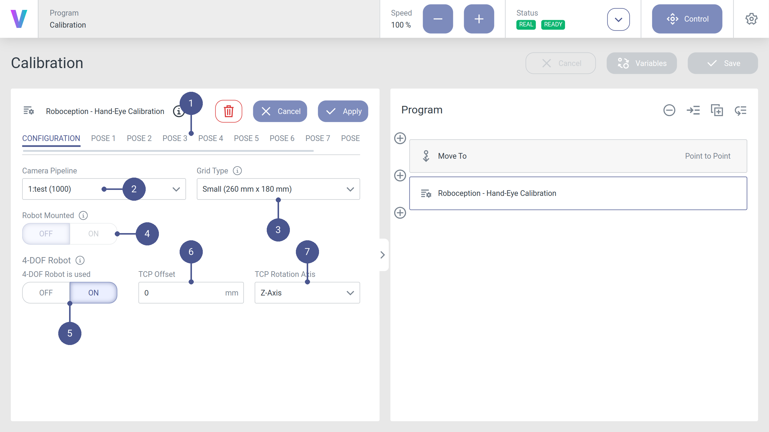
The following section describes how to parameterize the command while being in the Modify mode. Navigation between the different setup panels can be done by pressing the belonging tab in the voraus.operator (Fig. 13/➊).
Configuration
- Camera Pipeline:
The pipeline ID of the camera to use (Fig. 13/➋).
- Grid Type:
The size of the calibration grid (Fig. 13/➌).
- Robot Mounted:
Whether the camera is mounted onto the robot (Eye-In-Hand) or is mounted in a fixed position relative to the robot (Hand-In-Eye) (Currently only statically mounted cameras are supported) (Fig. 13/➍).
- 4-DOF Robot:
If the robot only has four degrees of freedom, e.g. a SCARA robot, the following parameters have to be set (Fig. 13/➎).
- TCP Offset:
The signed offset from the TCP to the camera coordinate system (robot-mounted sensor) or the visible surface of the calibration grid (statically mounted sensor) along the TCP rotation axis in meters (Fig. 13/➏).
- TCP Rotation Axis:
The axis of the robot frame around which the robot can rotate its TCP (Fig. 13/➐).
Pose Definition
Up to nine poses can be defined that will be used for the Hand-Eye Calibration (Fig. 14/➊). Each pose can be toggled by the Use Pose switch (Fig. 14/➋) and can be configured by defining the pose in joint space (Fig. 14/➌). At least four poses are required for the calibration. For detailed information about the optimal selection of poses, please refer to the Roboception Hand-Eye calibration documentation.
Note
To move the robot to a new calibration pose, it is recommended to first switch the camera streaming mode in the Roboception settings to Hand-Eye Calibration (see Configuring the Roboception Settings) and then open the Control Panel with the camera stream (Fig. 14/➍). That way you can move the robot while seeing the live detection of the grid. Once you are satisfied with the current pose, you can click on Get Pose to save it in the current pose configuration (Fig. 14/➎).
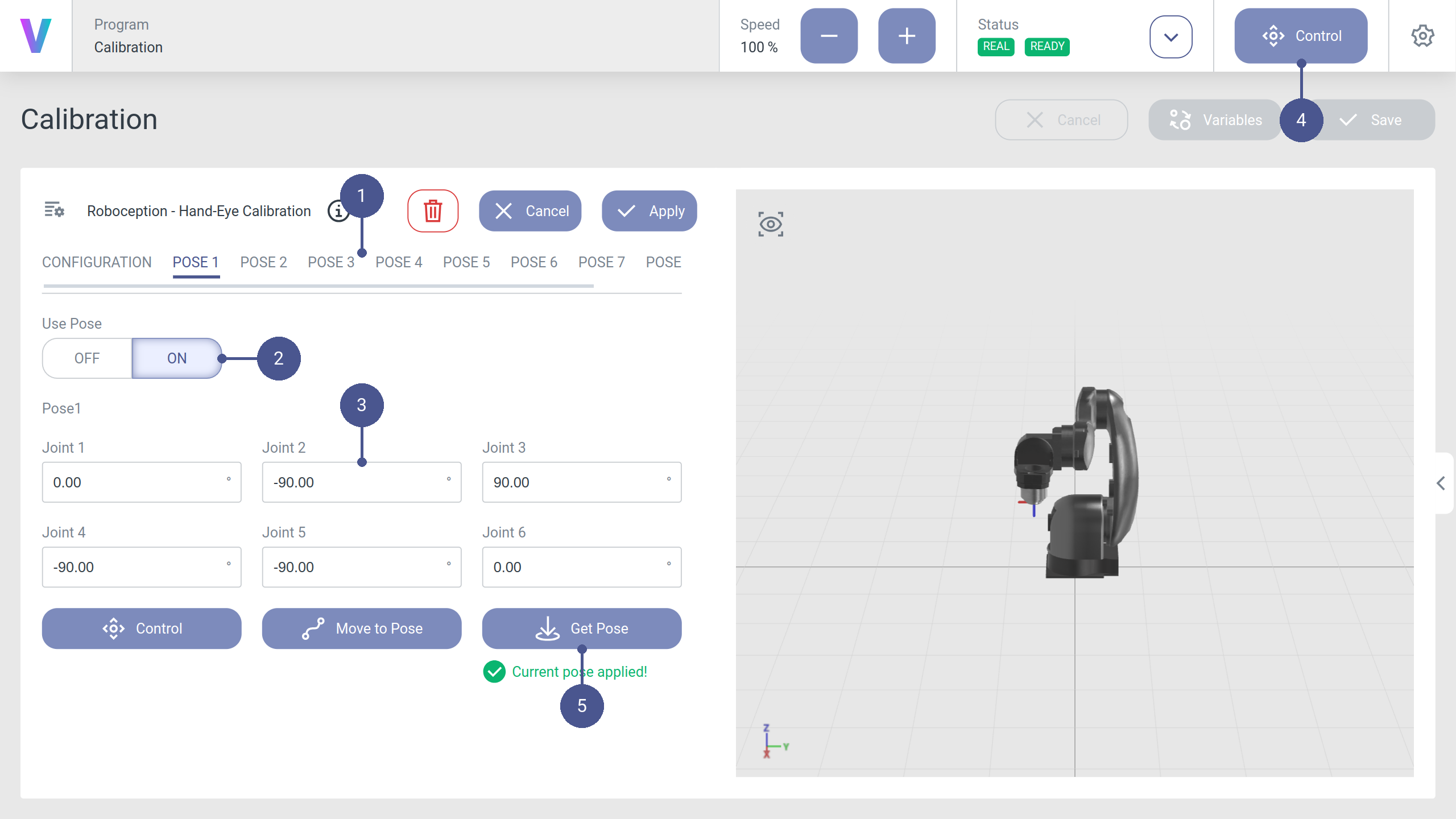
Fig. 14 The pose configuration tab of the Hand-Eye-Calibration command.
Runtime behavior
Once you configured your poses, you can execute the application. The robot will automatically move to the specified poses, store the camera images and calculate the Hand-Eye transformation. All disabled poses will be skipped during the execution of the calibration application. If the calculation of the Hand-Eye Calibration is successful it will be directly saved onto the camera. You can review the camera transformation and the accuracy in the application log or in the Roboception GUI.
Warning
While executing the application, the robot will move directly from one pose to the next one. Please choose the poses in a way that no collisions can occur during the movement.
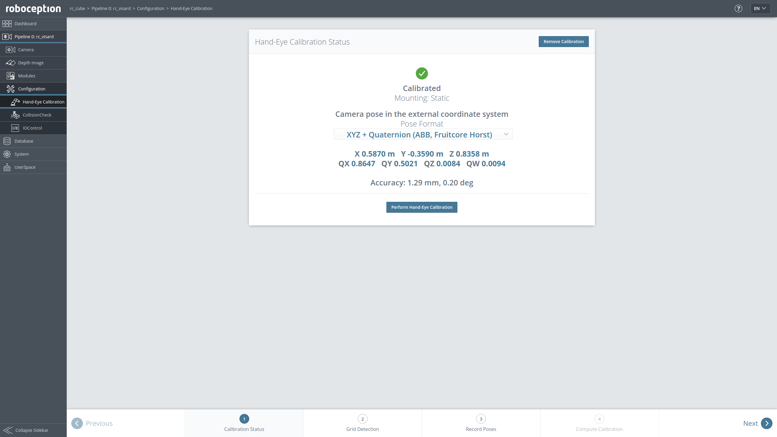
Fig. 15 Image of the estimated Hand-Eye transformation in the Roboception UI.
Errors
Note
This section is work in progress and might be incomplete. More error codes will be implemented soon. Meanwhile, you can debug with the raw exception messages.