5. Tutorials
5.1. Custom Commands
5.1.1. Introduction
The tutorial demonstrates how Custom Commands simplify the program creation.
Within the tutorial a program is created from scratch using Custom Commands. As example application the deburring of a wheel rim with a deburring tool is considered. (Fig. 93).
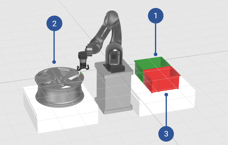
Fig. 93 Example application
In detail,
the deburring tool has to be taken from the green box (Fig. 93/➊),
moved around the wheel rim (Fig. 93/➋) and
be placed in the red box (Fig. 93/➌).
The tool is picked up and held by the gripper mounted to the robot flange.
Note
Throughout the tutorial only the gripper is shown but not the deburring tool.
While this tutorial will guide you through all the steps of the implementation, you can also find the final version of the program in the Examples directory of the Virtual Evaluation Docker Image.
5.1.2. Getting Started
Requirements
3D Visualization
For better illustration and to improve understandability, the visualization is populated with the objects described and
shown in Fig. 93.
To display the 3D objects in the visualization, the files describing the 3D objects and their location have to be moved
to the /srv/voraus/voraus-hmi/assets/environments folder as sub-folder.
Alternatively, if you use the Virtual Evaluation Docker Image, the scene wheel_rim_with_boxes is already installed
and can be activated as described in the Load a preinstalled voraus.operator scene tutorial.
Note
The 3D objects are not required to replicate the tutorial. All poses and motions work with and without the 3D objects present.
Gripper
The application uses the Robotiq_2F-85 gripper. To activate the gripper, open the Settings (Fig. 94/➊) and select Tools (Fig. 94/➋). In the tool list search for the Robotiq_2F-85 gripper and activate it (Fig. 94/➌). If you try to execute the program without activating the correct gripper, an error will be raised.
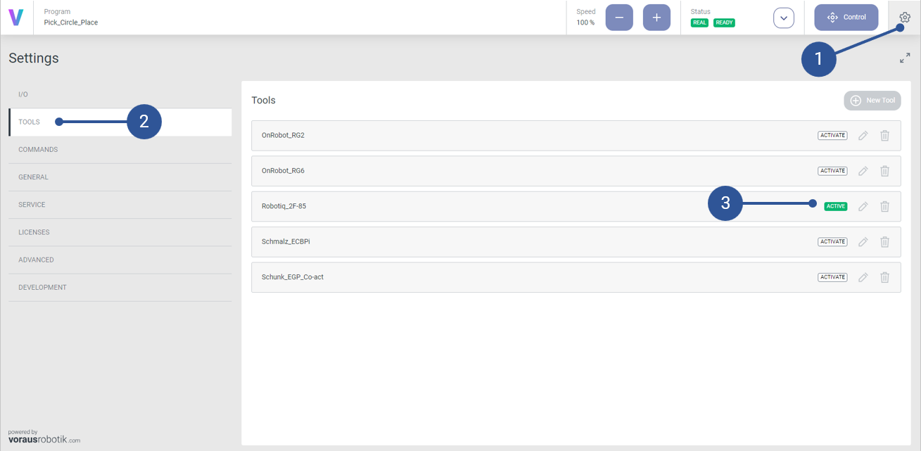
Fig. 94 Gripper activation
Custom Commands
The tutorial requires the Custom Commands:
Move Circular,
Handling - Pick Object and
Handling - Place Object.
All required Custom Commands are part of the virtual setup and can be found under Settings (Fig. 95/➊) in the Commands (Fig. 95/➋) tab. If required, add the Custom Commands by clicking the Import icon (Fig. 95/➌).
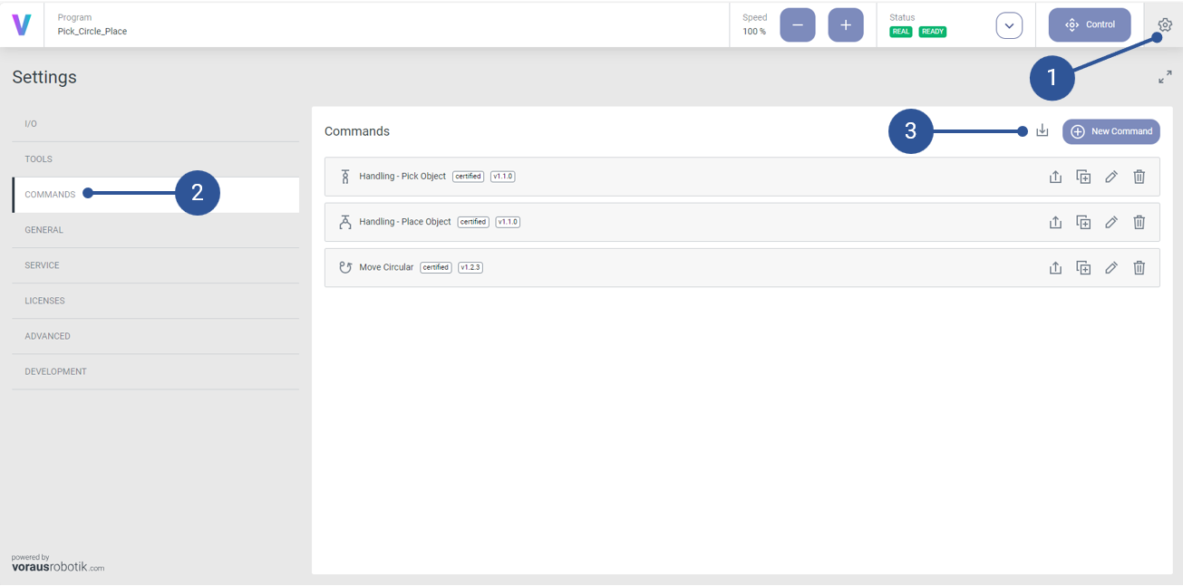
Fig. 95 Import Custom Commands
5.1.3. Implementation Steps
First let’s create an empty program which afterwards is edited step by step to the needs of the application.
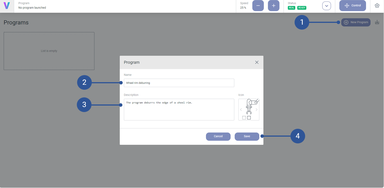
Fig. 96 Create empty program
To create a new program, go to the home screen and click the New Program button (Fig. 96/➊). Give the program an expressive name (Fig. 96/➋) and description (Fig. 96/➌). Afterwards, save the program (Fig. 96/➍).
The application consists of the following major steps:
picking the tool from the green box,
moving the tool along the edge of the wheel rim, and
placing the tool in the red box.
For each of these steps its favorable to have a pre-action-pose and post-action-pose above the pose at which the actual action (like pick, place, etc.) is performed (“action-pose”). With the help of the pre/post-action-poses collisions, etc. can be avoided.
For the application at hand the Custom Commands provided by voraus robotik can be used:
Handling - Pick Object,
Handling - Place Object, and
Move Circular
The provided Custom Commands simplify the program creation for the application significantly, for example, by implementing and encapsulating all necessary movements between the pre-/post-action-pose and the action-pose.
As demonstration compare Fig. 97/➊, showing the program for step 1 without the Custom Command Handling - Pick Object, and Fig. 98/➊, showing the program for step 1 with the Custom Command Handling - Pick Object.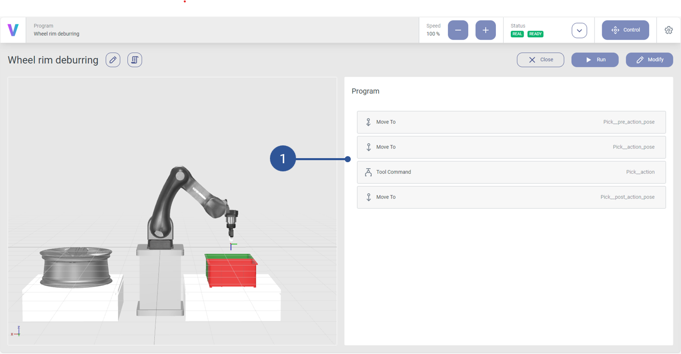
Fig. 97 Step 1 without the Custom Command Handling - Pick Object

Fig. 98 Step 1 with the Custom Command Handling - Pick Object
By just adding the Handling - Pick Object Custom Command all required sub-commands for step 1 are automatically included in the program.
Continuing the program creation it seems reasonable to choose the same pose for the pre-action-pose and post-action-pose and to define the pre/post-action-pose relative the action-pose. In other words, the following settings of the Handling - Pick Object Custom Command have to be adapted:
The pick-pose (Fig. 99/➊)
The Configuration Method, to tell the command that the pre-action-pose and post-action-pose are equal and defined relatively to the action-pose. (Fig. 100/➊)
The offset for the pre/post-action-pose defined relatively to the action-pose (Fig. 100/➋).

Fig. 99 Step 1: Set pick-pose
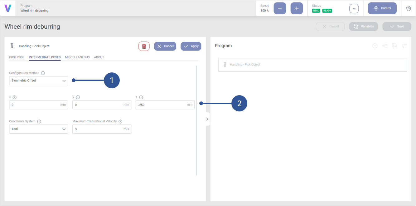
Fig. 100 Step 1: Set pre/pose-pick-pose
For step 2 one can use the Custom Command Move Circular. The Move Circular provides a clean and easy to use UI interface for a circular move command, otherwise, only accessible via the voraus Python-API. Due to its complexity, the Move Circular command does not provide a pre-action-pose and post-action-pose, and the corresponding move commands. Therefore, one has to define these sub-commands manually. To keep the program readable and clean, a group command should be created in which all commands regarding the circular motion around the wheel rim are added. In other words, the group command shall contain the following commands (Fig. 101/➊):
a PTP command to the pre-action-pose
(pre-action-pose: Joint CS = [-200.21, -83.59, -142.39, -44.02, 90.00, 110.21] | Robot CS = [400, 0, 10, -180, 0, 0]),a linear command to the action-pose
(action-pose: Joint CS = [-200.21, -94.11, -146.37, -29.51, 90.00, 110.21] | Robot CS = [400, 0, -50, -180, 0, 0]),a command to perform the circ action
(center-pose: Joint CS = [-191.39, -123.54, -100.04, -46.42, 90.00, 101.39] | Robot CS = [700, 0, -50, -180, 0, 0]), anda linear command to the post-action-pose
(post-action-pose: Joint CS = [-200.21, -83.59, -142.39, -44.02, 90.00, -249.79] | Robot CS = [400, 0, 10, 180, 0, 0]).
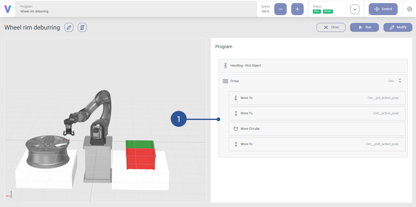
Fig. 101 Step 2: Commands
The Move Circular command provides different options to define a circular motion and many more parameters to tune the command to the needs of the application. For the application it seems reasonable to define the circle via the Angle And Center method (Fig. 102/➊).
Using the Angle And Center method, one defines the center of the circle (Fig. 102/➋), the angle of the segment which should be covered by the path, as well as the rotational direction (Fig. 102/➌).
Fig. 102 Step 2: Circ parameterization
For the tool orientation along the edge of the wheel rim, it seems reasonable to choose the Orientation Interpolation option Constant to path (Fig. 103/➊). The Constant to path ensures that the tool always keeps a constant orientation with respect to the circle along the circular path.
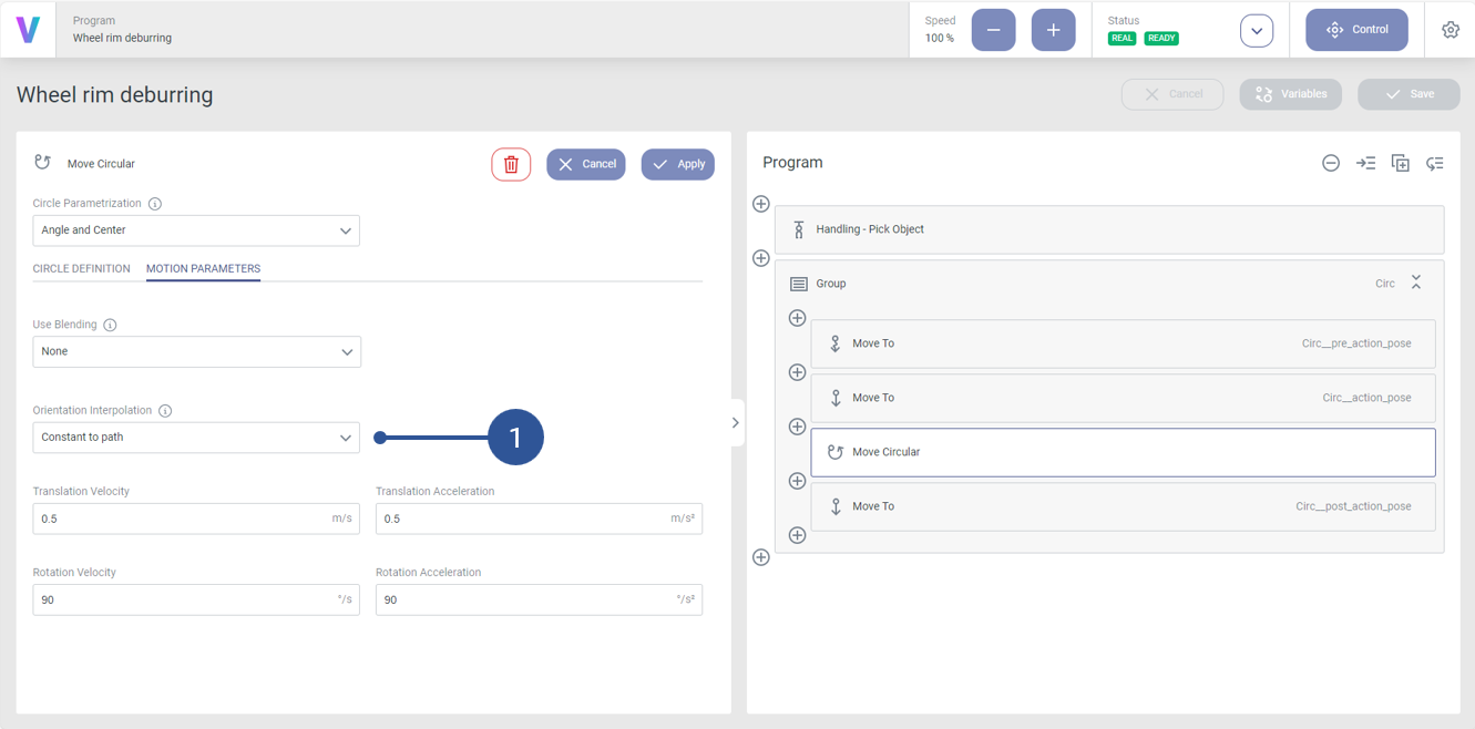
Fig. 103 Step 2: Circ orientation interpolation
Finally, in step 3 the tool must be placed in the red box. Similar to step 1 the pre-action-pose is chosen equal to the post-action-pose and defined relatively to the action-pose (Fig. 105/➊ + ➋). The action-pose is chosen as shown in Fig. 104/➊. However, instead of the Custom Command Handling - Pick Object, the Custom Command Handling - Place Object is used.
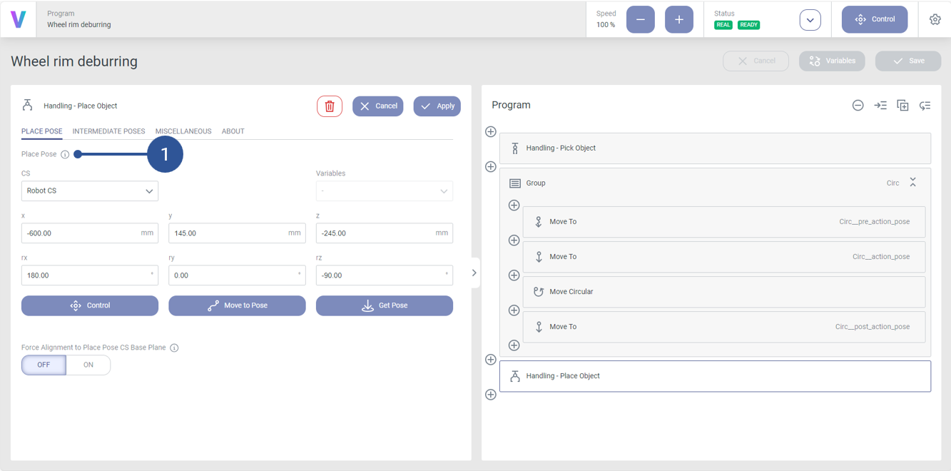
Fig. 104 Step 3: Set place-pose
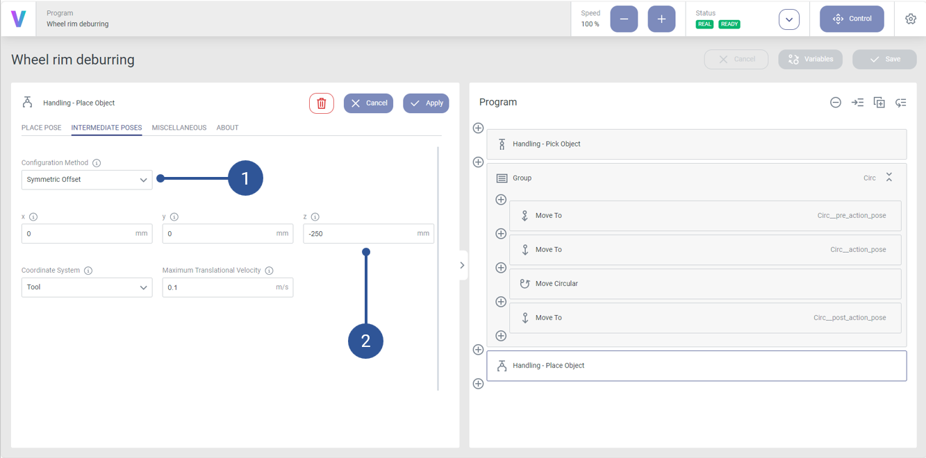
Fig. 105 Step 3: Set pre/pose-place-pose
5.1.4. Video
The following video shows the final application created in the tutorial.
5.2. Load a preinstalled voraus.operator scene
5.2.1. Introduction
The Virtual Evaluation Docker Image is shipped with predefined scenes that are ready to use. Some examples can be
seen in Fig. 106.
The scenes can only be loaded if no other scene is defined
in the /srv/voraus/voraus-hmi/assets/environments directory,
as it is described in the Install 3D Assets tutorial.
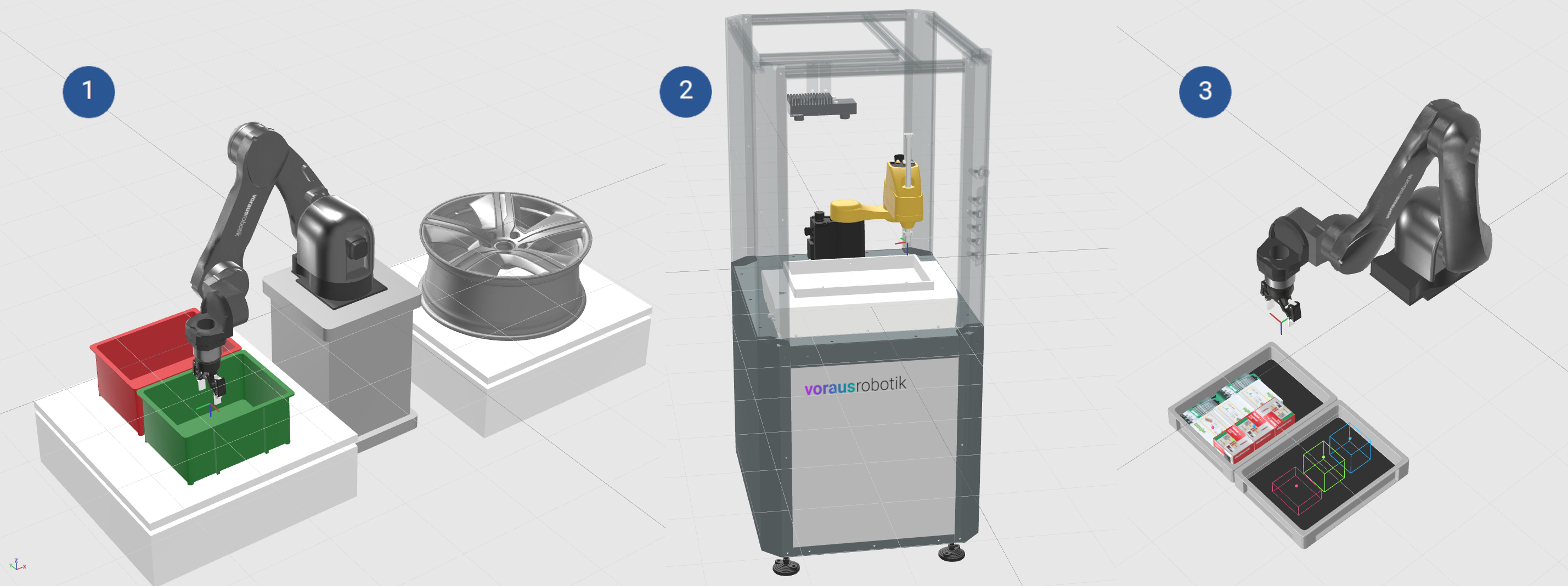
Fig. 106 voraus.operator scene examples:
➊ wheel_rim_with_boxes,
➋ small_automation_cell,
➌ pioneer_example
|
Description |
|---|---|
wheel_rim_with_boxes Fig. 106/➊ |
Two colored boxes and a rim. Used in the Wheel rim deburring example program. Best suitable for robots with a larger workspace. |
small_automation_cell Fig. 106/➋ |
Closed and transparent cell with a camera and a VarioShaker. Best suitable for robots with a small workspace like FANUC SR-3iA. |
pioneer_example Fig. 106/➌ |
Two load carriers with various boxes and rendered target positions. |
5.2.2. Getting Started
In order to activate one of the scenes, the environment variable OPERATOR_ENVIRONMENT has to be set to one of
the values from Table 2.
This can be done in the environment section of the docker compose file
(described in Docker Compose Environment).
Listing 2, for instance, shows how to configure a docker_compose.yml to change the scene
to small_automation_cell
 version: "3.3"

 services:
   ...
   voraus-core:
     ...
     environment:
       ...
+      # Select a voraus.operator scene
+      OPERATOR_ENVIRONMENT: "small_automation_cell"
   ...
The variable is set to wheel_rim_with_boxes by default, so this scene is active in case you did not modify or unset
the variable.
5.2.3. Troubleshooting
The loading of the scene is logged right at the start of the docker container. Reviewing the container log (as described in View Logs from Portainer) can indicate potential issues.
The loading of a predefined scene is skipped if:
The environment variable
OPERATOR_ENVIRONMENTis not setNo matching scene exists for the content of the
OPERATOR_ENVIRONMENTvariable. See list of Available voraus.operator Scenes.The
/srv/voraus/voraus-hmi/assets/environmentsdirectory is not empty during the start of the container. Check whether a volume or bind mount is attached to this directory.