2. voraus.operator
To open the voraus.operator, please open a browser, it is recommended to use Chrome. If you use the default configuration, please type in the following IP address: https://192.168.1.1:8080
2.1. User interface overview
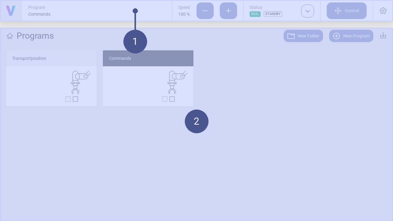
Fig. 7 User interface structure
➊ Navigation bar ➋ Work window
The user interface consists of the navigation bar (Fig. 7/➊) and the work window (Fig. 7/➋). The work window and its content change dynamically. Exemplary, the home screen is shown in the work window providing a quick access to applications.
In addition to the creation and management of programs, this includes manually moving of the robot and setting of the robot parameters. The navigation bar is displayed in every screen and contains the following basic commands in addition to the status message of the robot:
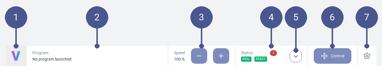
Fig. 8 Navigation bar
Fig. 8/➊ |
Logo - Return to the home screen |
Fig. 8/➋ |
Program - Displays the active program. Click to open it. |
Fig. 8/➌ |
Speed - Adapt the speed of the robot. The maximum value of 100 % the upper limit set in the settings / commands. |
Fig. 8/➍ |
Status - Displays the status of the robot. Clicking the button opens the status corresponds to menu. |
Fig. 8/➎ |
Status Quick Access - Opens the quick access menu for the operation of the robot. |
Fig. 8/➏ |
Control - Opens the manual control menu. |
Fig. 8/➐ |
Settings - Opens the settings menu. In this menu, the parameters of the robot can be set. |
2.1.1. General Settings
In the general settings, personal adjustments can be made, such as selecting the language and system specific information are provided. Use the following steps to navigate to the general settings page:
Click on the Settings Icon to open the settings page.
Click General in the settings menu.
Language
The language can be changed with opening the dropdown menu and selecting the desired language. Supported languages are English, German, Chinese, Japanese.
Drag & Dop
Activate or deactivate the function to drag & drop commands
Software Version
See the latest software version
2.2. Operating the robot
2.2.1. Switch off the voraus.core
The voraus.core can be switched off in the user interface.
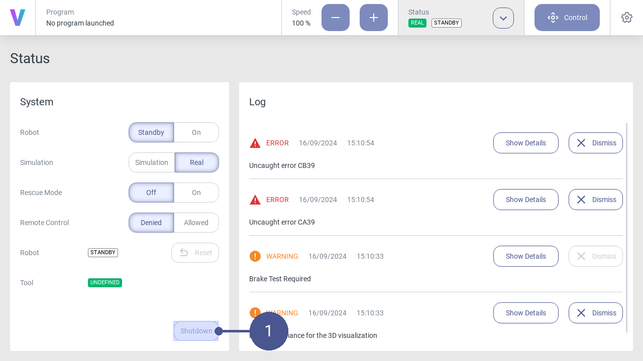
Fig. 9 Status menu
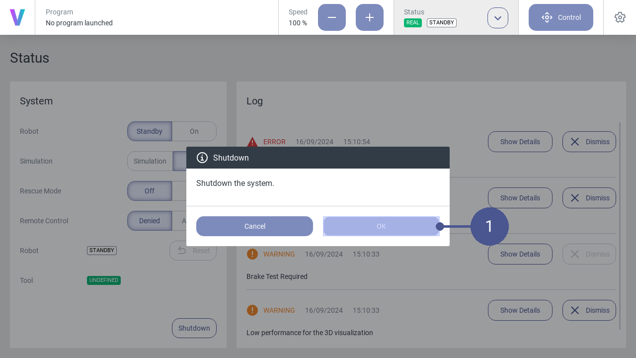
Fig. 10 Switch off the voraus.core
2.2.2. Manage programs
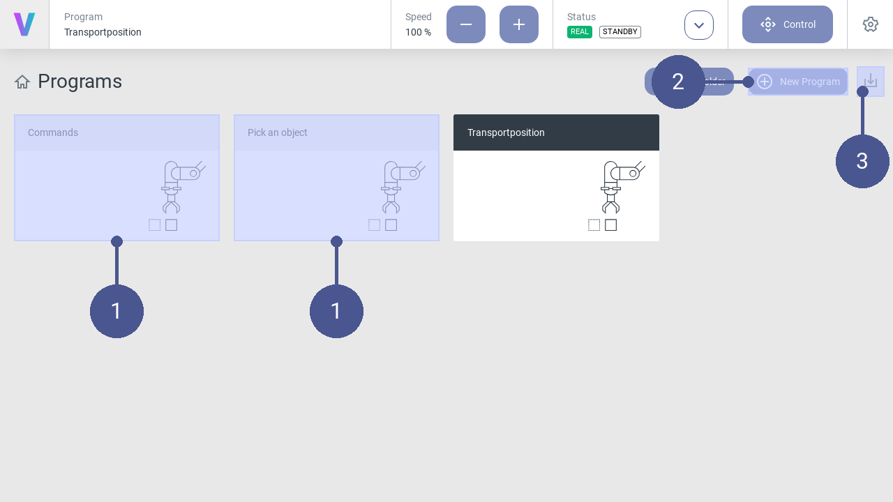
Fig. 11 Home screen
Programs (Fig. 11/➊) are displayed on the home screen of the user interface.
A new program can be created via the New Program button (Fig. 11/➋). Programs can be imported via the Import Program button (Fig. 11/➌).
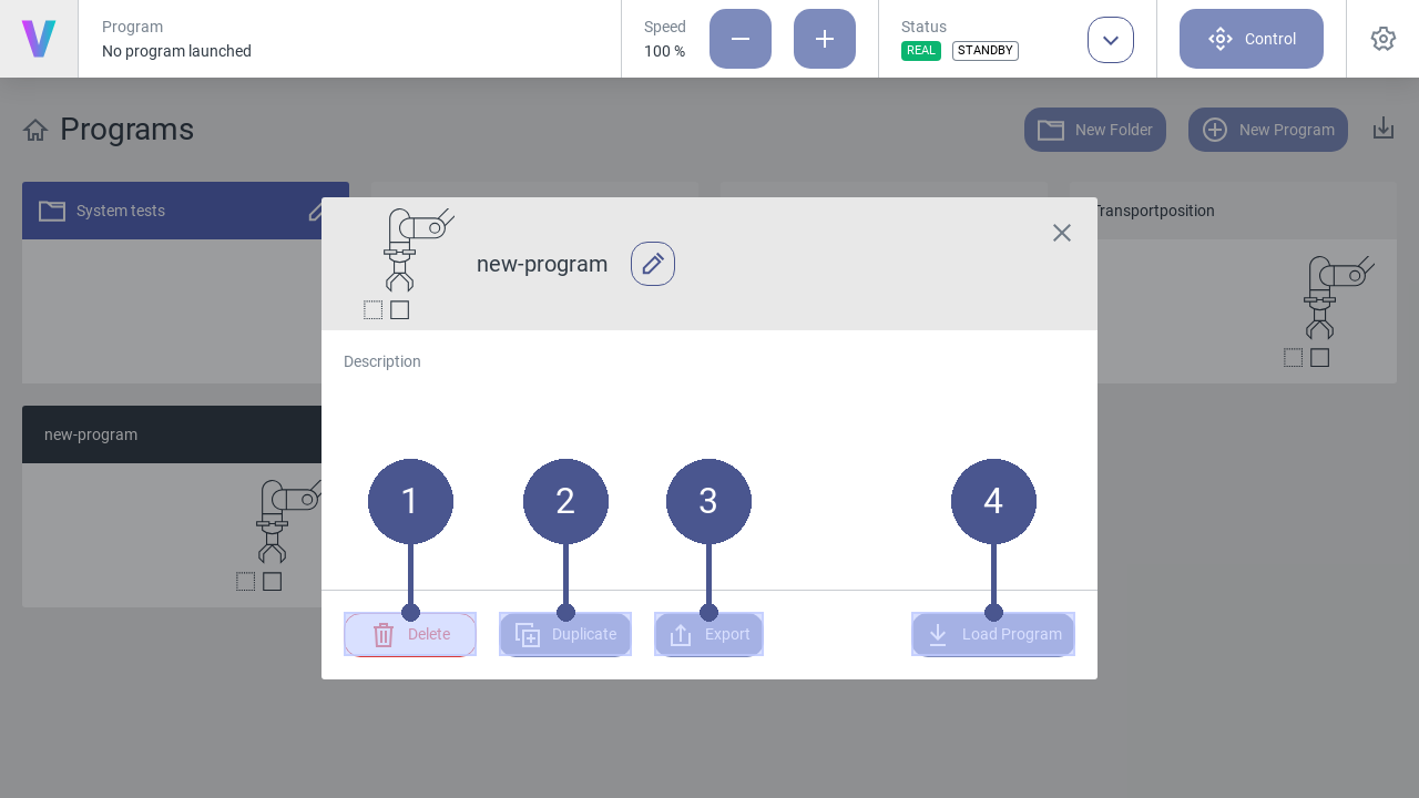
Fig. 12 Manage programs
To manage existing programs, click on the desired program on the main screen.
Note
The menu (Fig. 12) opens.
Click on one of the following buttons:
Fig. 12/➋ |
Delete - Delete the selected program. |
Fig. 12/➋ |
Duplicate - Copy the selected program. |
Fig. 12/➌ |
Export - Export the selected program. |
Fig. 12/➍ |
Load Program - Load the selected program. |
Folders
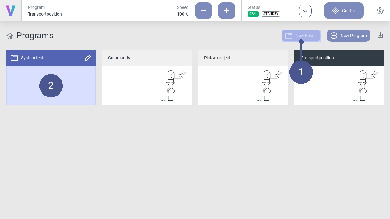
Fig. 13 Manage folders
Folders can be created on the home screen in addition to programs. They are useful for grouping and sorting programs.
To create a new folder:
Press the New Folder button (Fig. 13/➊).
Enter a meaningful name.
Press the save icon.
Programs can be moved to folders (Fig. 13/➋) via drag and drop. To move a program out of a folder, it must be dragged and dropped onto the navigation title Programs.
It is possible to rename and delete folders by clicking the edit icon. Please note deleting a folder deletes all included programs too. This cannot be undo. Folder cannot be deleted when an included program is currently loaded.
2.2.3. Configure Digital Inputs & Outputs
The digital inputs and outputs are located within the I/O section in the settings menu Fig. 14. On the I/O page, all inputs (In) and outputs (Out) are displayed.
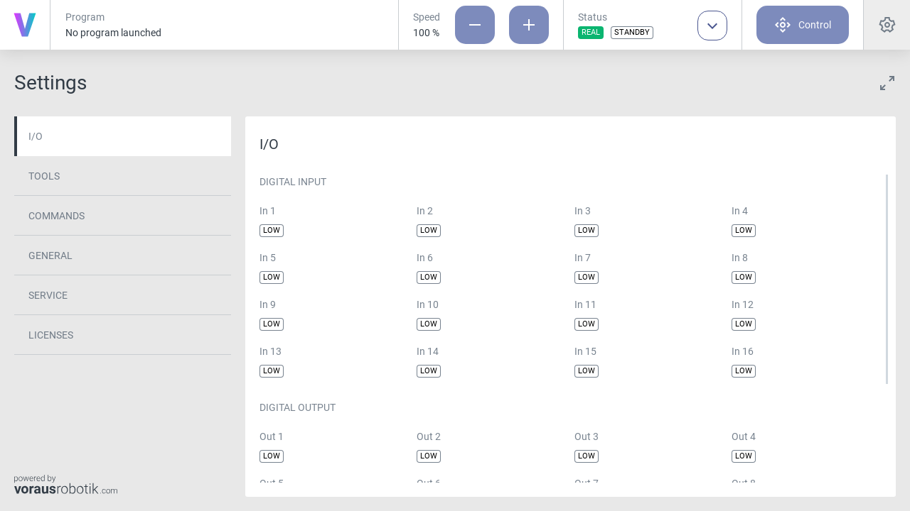
Fig. 14 Digital inputs & outputs overview
The status of each digital I/O channel can be in one of two states:
LOW: The I/O signal is at a low voltage level, typically representing an off or inactive state.
HIGH: The I/O signal is at a high voltage level, typically indicating an on or active state.
Digital Inputs
Digital inputs are used to receive signals from external devices or sensors. These inputs are essential for capturing data from your environment or interacting with other equipment like for example conveyor belts or light barriers.
Digital Outputs
Digital outputs are used to control external devices or machines, allowing the voraus.core to trigger actions in response to its programmed tasks. Digital outputs can be configured in multiple ways:
Clicking on the status badge of a digital output on the I/O page, to toggle the value manually. By clicking the badge a popup will open to double check if you really want to change the value. Press OK to submit or press Cancel to discard the action.
Set one or multiple digital outputs in a program by using the Set Digital Outputs command.
Safety Precautions
When configuring digital inputs and outputs, ensure that all safety guidelines and protocols are followed. Incorrect I/O settings can lead to unintended actions or hazards. Always conduct thorough testing and verification to guarantee the robot’s safe operation.
2.2.4. Configure Tool
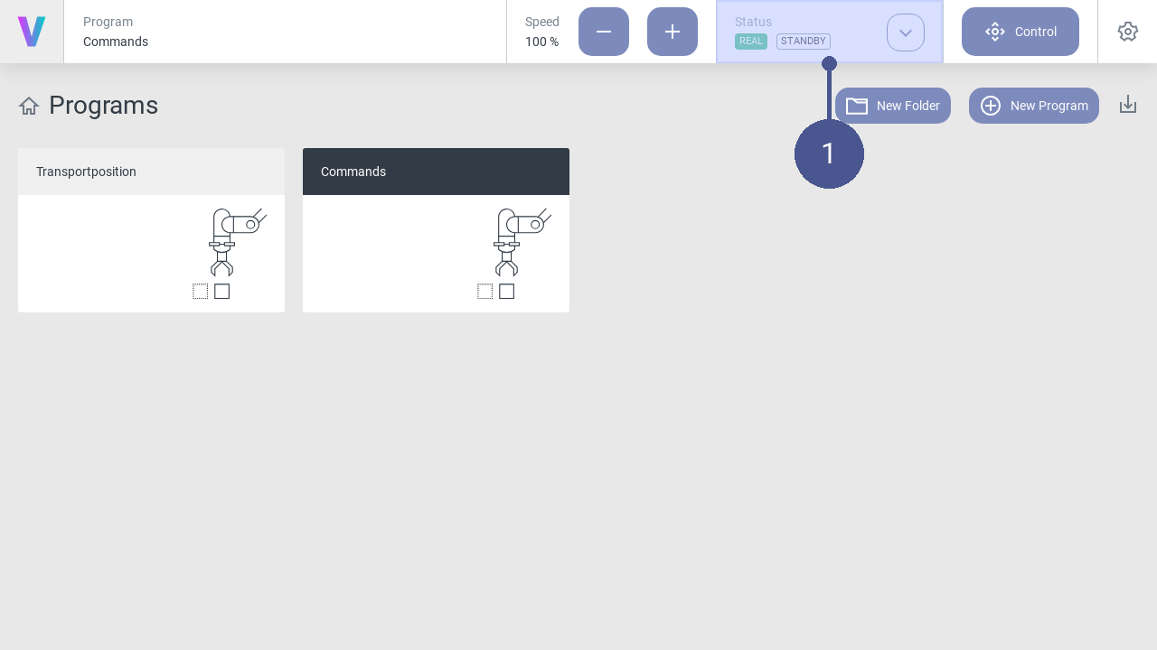
Fig. 15 Home screen
Click on the Status button on the home screen (Fig. 15/➊).
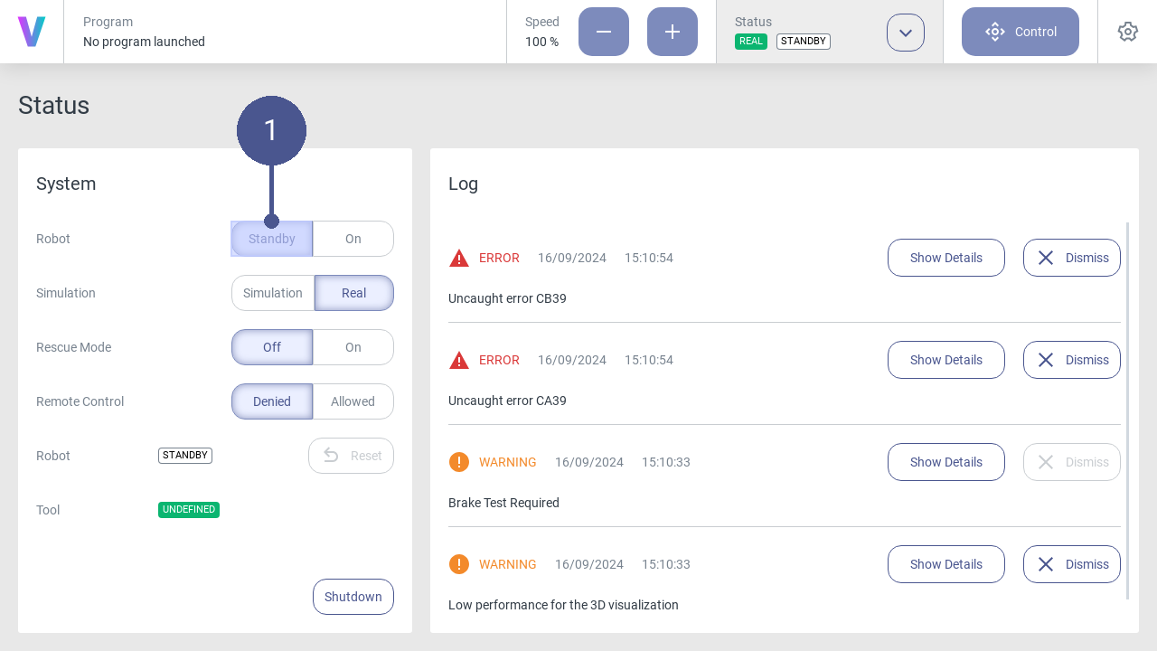
Fig. 16 Robot in standby mode
Click Standby in the status menu. (Fig. 16/➊)
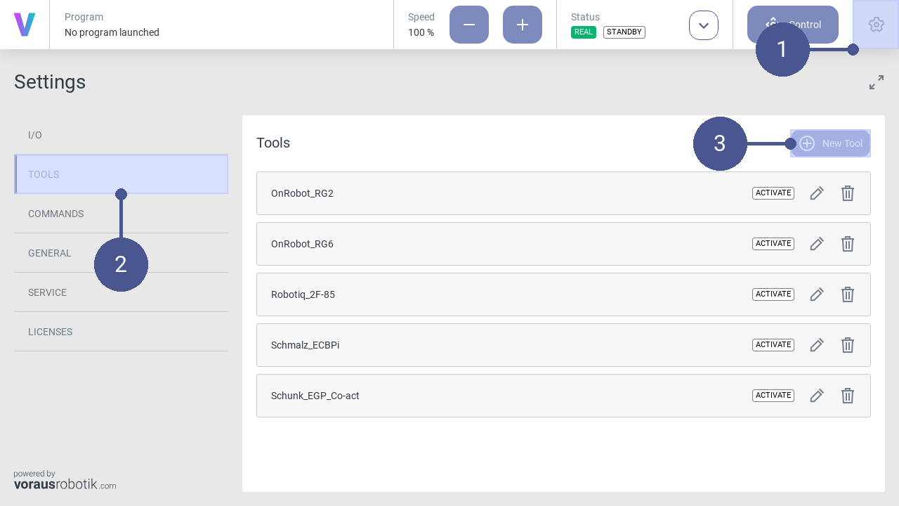
Fig. 17 Open the settings menu
Click the settings icon in the navigation bar (Fig. 17/➊), to open the settings menu.
In the settings menu, click on TOOLS in the left tab to open the window of the tool’s settings (Fig. 17/➋).
Click on New Tool (Fig. 17/➌).
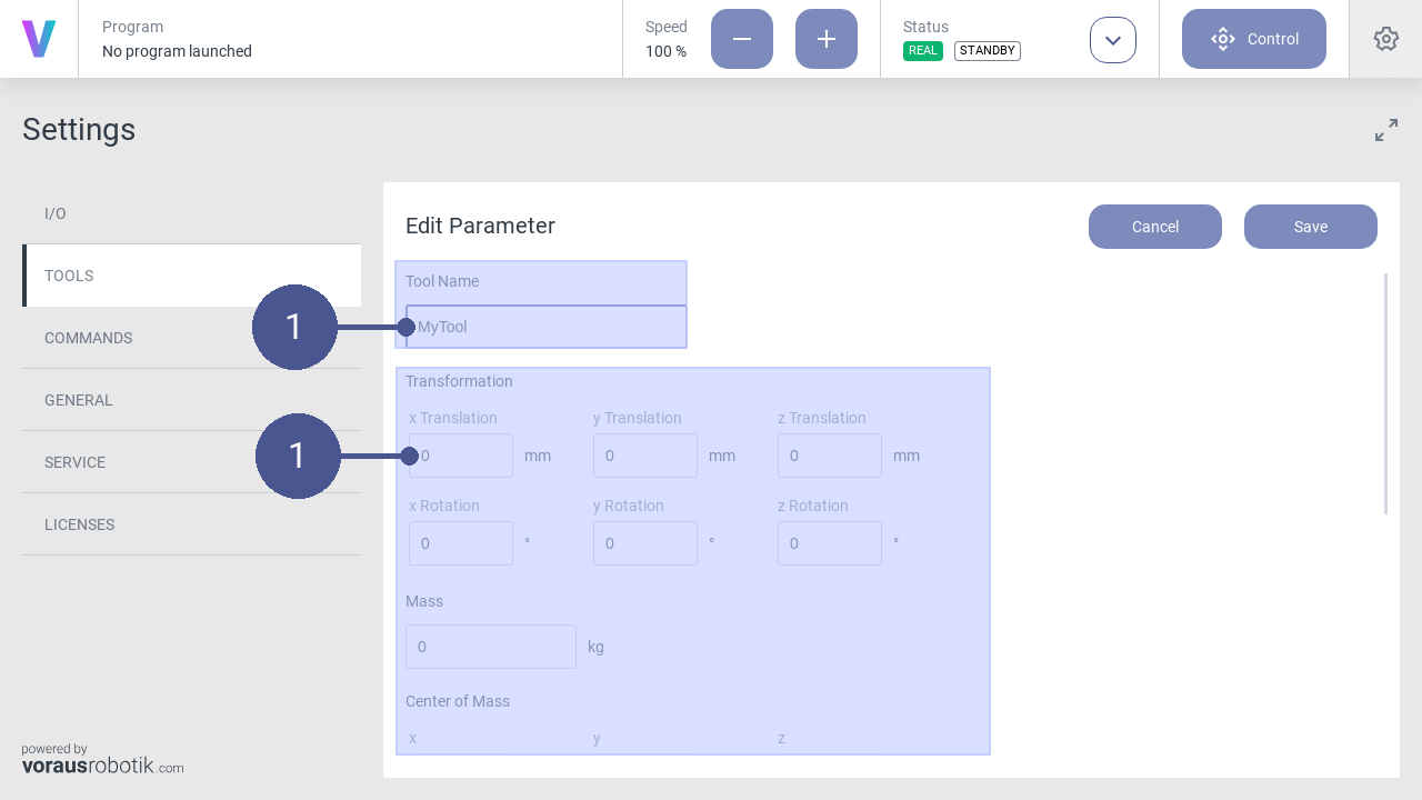
Fig. 18 Set tool parameters
Name the tool and enter its parameters (Fig. 18/➊).
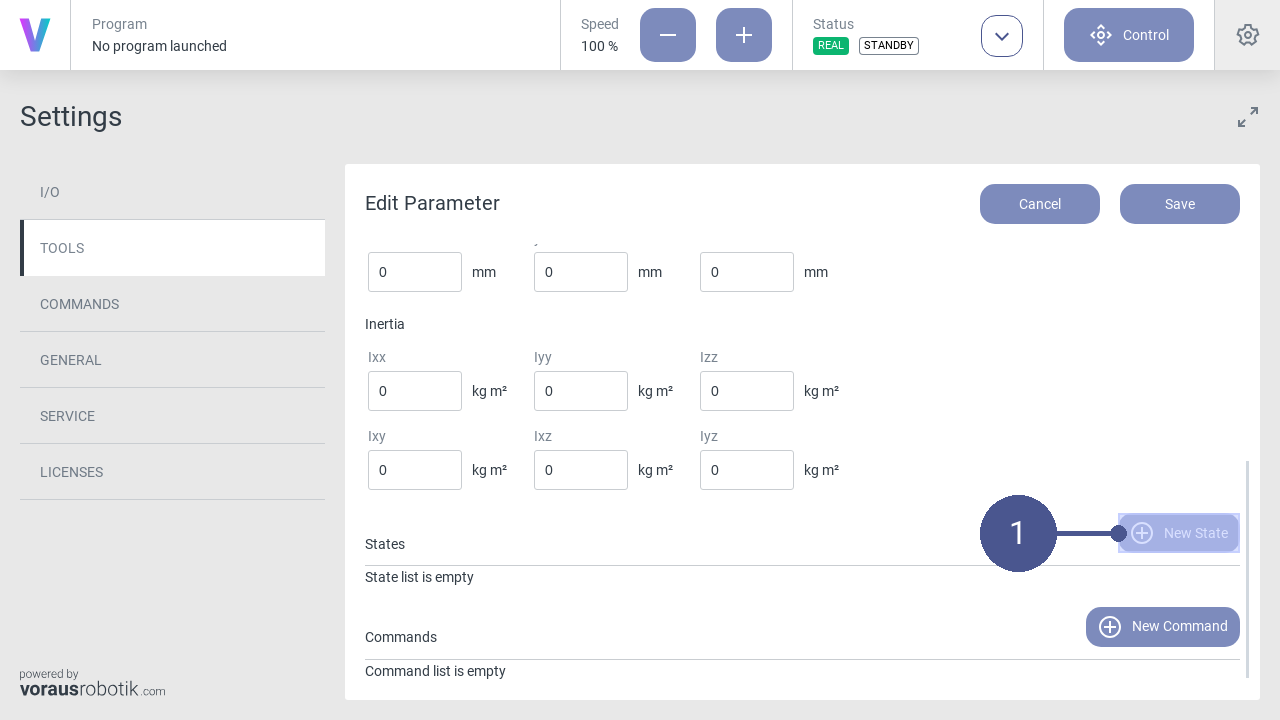
Fig. 19 Open the state menu
Click New State to open the state menu (Fig. 19/➊).
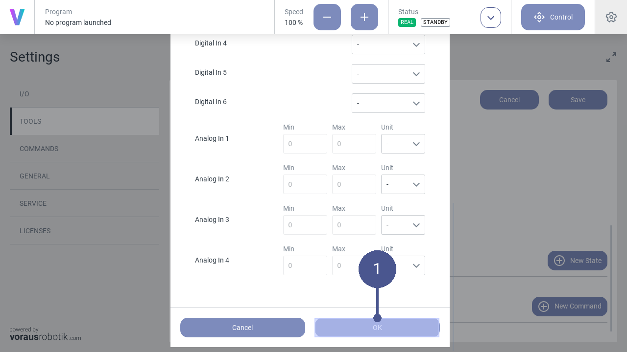
Fig. 20 Create state
8. In the state menu, define the states of the digital outputs and the digital inputs according to the operator’s specifications and confirm with OK (Fig. 20/➊).
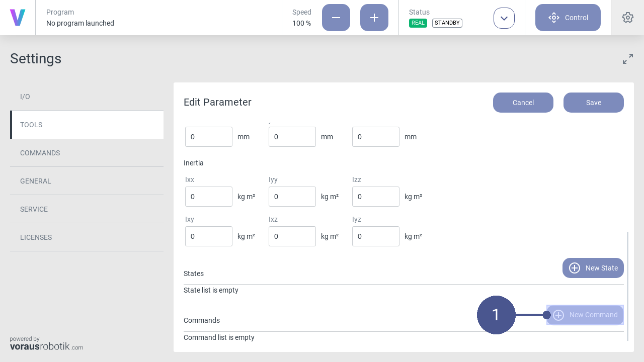
Fig. 21 Open command
Click New Command to open the command menu (Fig. 21/➊).
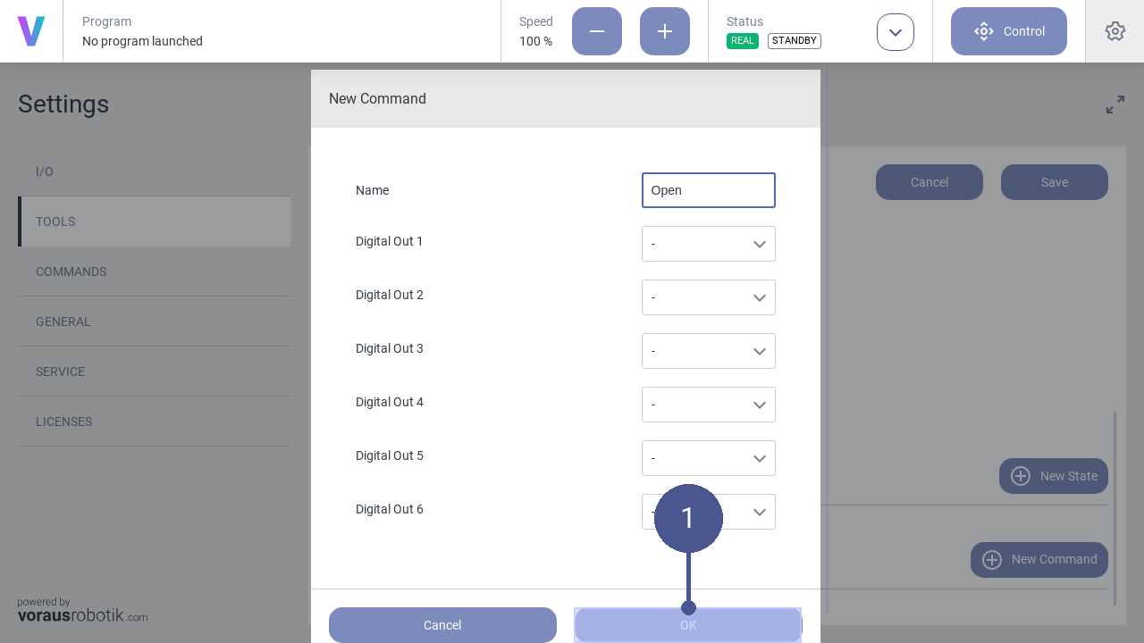
Fig. 22 Create command
In the command menu, define the states of the digital outputs according to the operator’s specifications and confirm with OK (Fig. 22/➊).
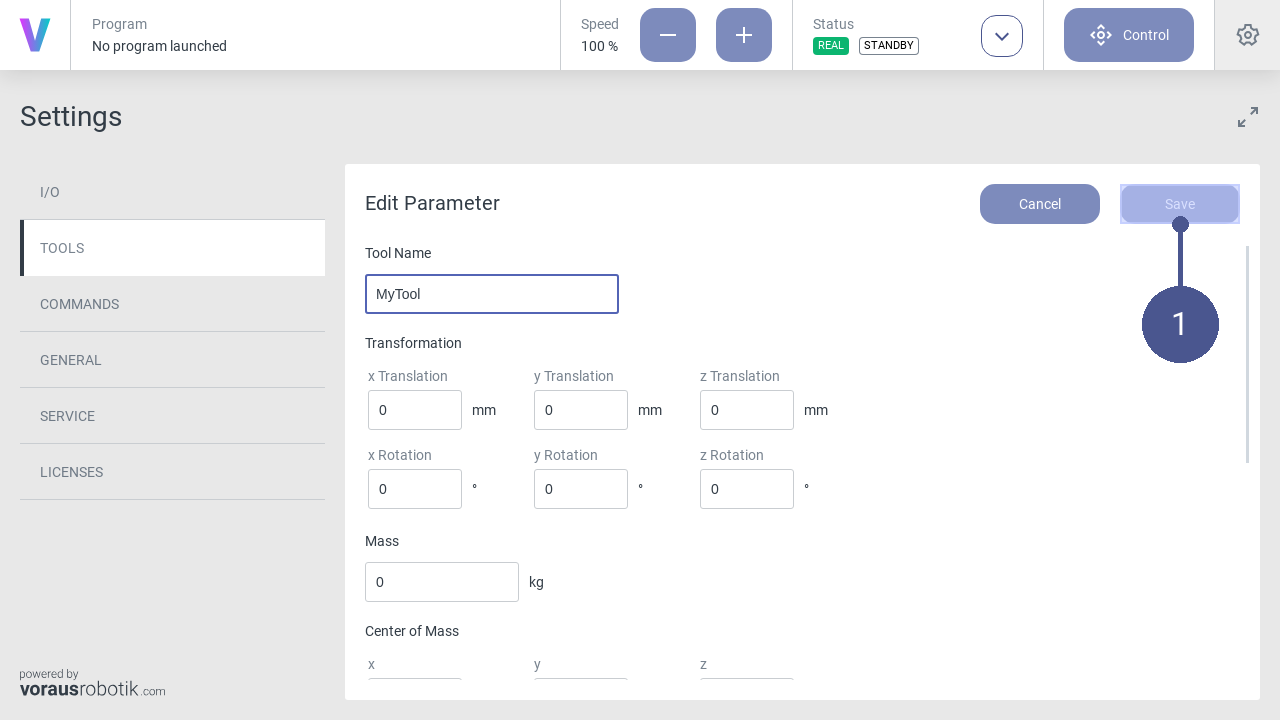
Fig. 23 Save tool parameters
Click Save to save the tool parameters (Fig. 23/➊).
2.2.5. Camera Settings
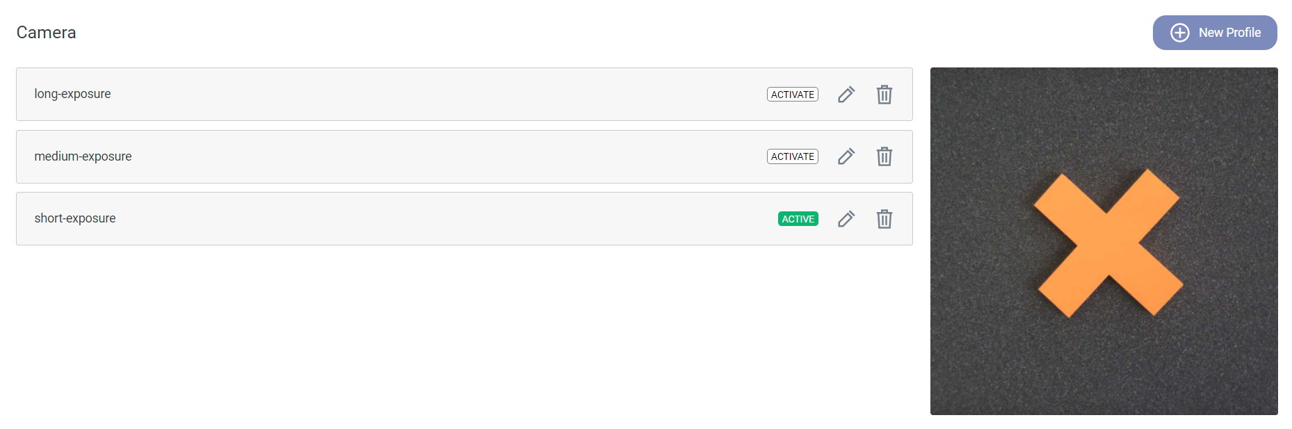
Fig. 24 Overview of the camera setting profiles
Description
Depending on the lighting conditions of the environment and the contrast between any objects and the background, it can
be beneficial to tweak the camera settings. You can edit the default camera settings and define new ones within the
settings menu. To access it, click the settings icon  in the top right corner of the HMI and select
the CAMERA section. All available camera setting profiles are listed in this menu. To create a new profile, press
the New Profile button on the right (see Fig. 24). To edit or delete
existing profiles, click the edit icon
in the top right corner of the HMI and select
the CAMERA section. All available camera setting profiles are listed in this menu. To create a new profile, press
the New Profile button on the right (see Fig. 24). To edit or delete
existing profiles, click the edit icon  respectively the delete icon
  next to the profile name. By
clicking the ACTIVATE badge you can switch between the defined profiles.
next to the profile name. By
clicking the ACTIVATE badge you can switch between the defined profiles.
Parameterization
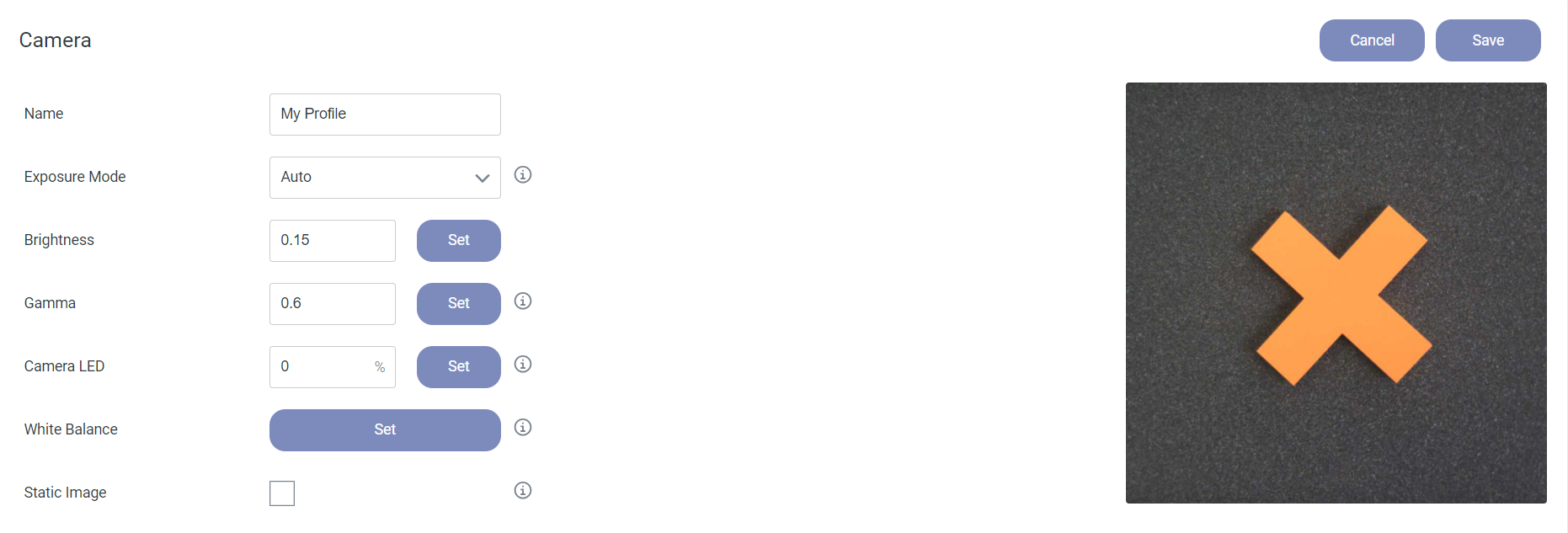
Fig. 25 Interface of a camera setting profile
Name: Enter a name for the profile.
Exposure Mode: Choose between “Manual” and “Auto”.
Auto: The exposure time is chosen automatically. You can adjust the overall brightness of the camera frame by editing the Brightness value. The brightness factor can be set to any value in the range from 0.1 to 1.0.
Manual: You can set the Exposure Time [µs] value manually. The valid range is 10 µs to 40.000 µs.
Gamma: Value for the gamma correction of the incoming camera frames. Higher values let the image appear brighter, lower values darker. The valid range is from 0.25 to 2.0.
Camera LED: Percentage of the LED brightness between 0 and 100. 0 means the LEDs are switched off.
White Balance: The Set button adjusts the white balance. For this the camera has to be targeted at a white surface. The white balance is used to eliminate tint and improve the accuracy of the color representation.
Static Image: If checked the execution of the vision command inside a program is delayed until no more movement is detected in the camera frame.
Save: Save the current camera settings.
Cancel: Discard any changes.
Values of the Default Settings
Exposure Mode |
Auto |
Brightness |
|
Gamma |
0.6 |
Camera LED |
0 |
Static Image |
Off |
Additional Information
By deleting all camera profiles, the three default settings short/medium/long-exposure are restored automatically.
The Static Image option can be useful in applications with high robot velocities.
2.2.6. Create a new program
Personnel: System integrator
Requirements
The safety configuration for the new program has been correctly parameterized by the system integrator.
The robot is in manual operating mode.
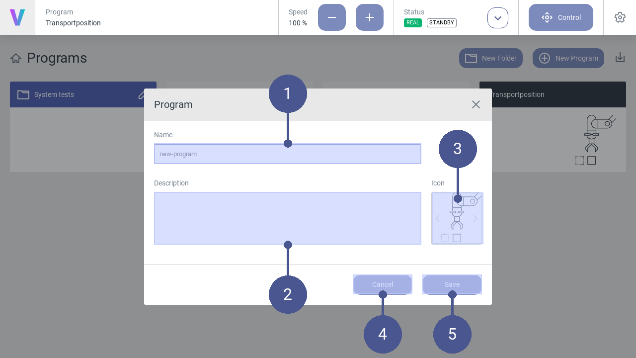
Fig. 26 Create new program
To create a new program, click New Program on the main screen. The menu (Fig. 26) opens.
Enter Name and Description of the program function (Fig. 26/➊ + ➋).
Select an appropriate Icon by using the arrows (Fig. 26/➌).
Click Save to create the program (Fig. 26/➎). Otherwise click Cancel to return to the main screen (Fig. 26/➍).
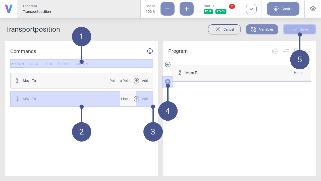
Fig. 27 Add commands to program
5. In the program menu (right half of the screen), define the program sequence by inserting individual command blocks (Fig. 27).
To do so, proceed as follows:
6. In the tab select the required command category by clicking on it (Fig. 27/➊). The following command categories are available:
MOTION
Define movement patterns of the robot.
VISION
Use the camera on the media flange, e.g. for object detection.
LOGIC
Select logic commands such as repeat, to execute a group of commands in a loop.
TOOL
Control the selected tool.
OTHER
Create a group of commands to improve the program´s readability.
CUSTOM
Apply your individual commands.
Select the desired command block (Fig. 27/➋) and add it to the program sequence by clicking on the plus symbol (Fig. 27/➌) The new command block is added to the program flow at the position of the colored cursor (Fig. 27/➍).
After assigning all the required command blocks, Save your final program and enjoy its impact (Fig. 27/➎).
The newly created program can be loaded and executed by the operator on the main screen.
2.2.7. Load and execute programs
Personnel: Operator
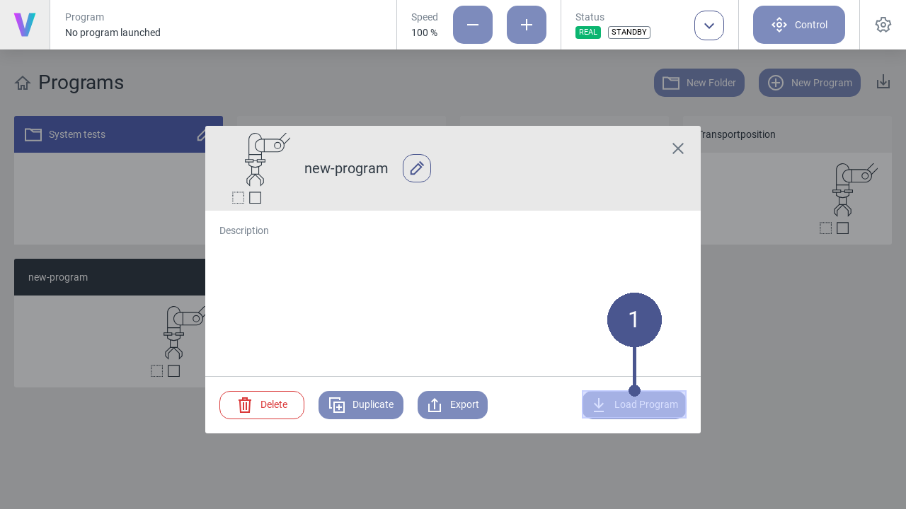
Fig. 28 Load program
To load a program, click on the button of the desired program on the home screen.
Note
The pop-up (Fig. 28) opens.
2. Click the Load Program button to open the selected program (Fig. 28/➊).
In the program menu (Fig. 29), the program sequence is displayed as a sequence of the individual command blocks (Fig. 29/➋).
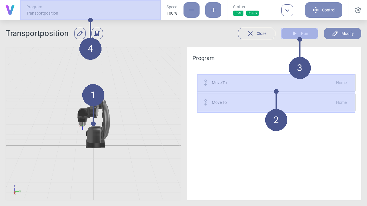
Fig. 29 Start program
To start the program, click Run (Fig. 29/➌).
The robot executes the program according to the sequence of the command blocks.
Note
Virtual robot
In the left menu section, the movements are displayed using a virtual robot model (Fig. 29/➊). In the navigation bar, the currently loaded program is displayed at any time (Fig. 29/➍).
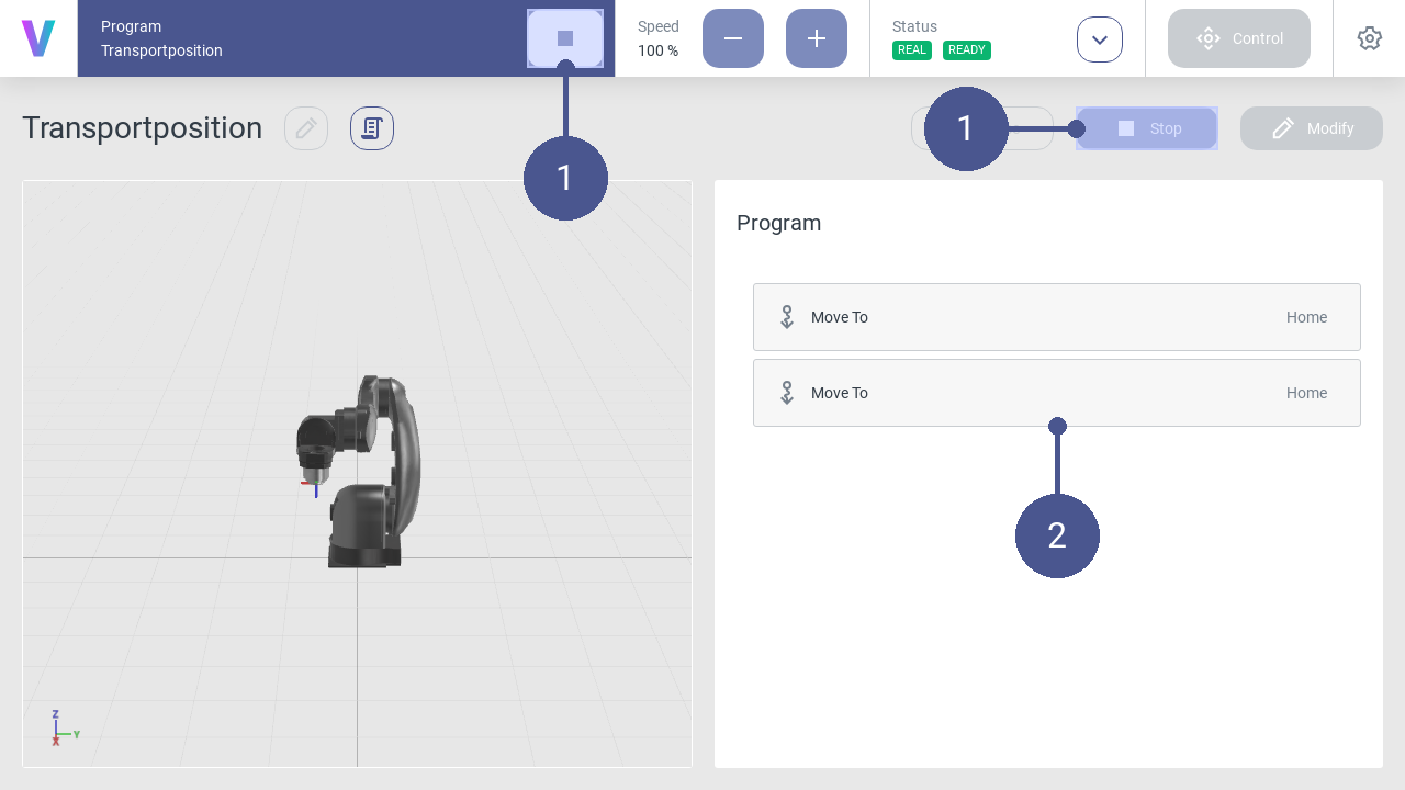
Fig. 30 Stop program
To stop the program, click the Stop button in the navigation bar or the program menu (Fig. 30/➊).
Note
Program sequence
The currently executed command sequence is displayed via a colored time bar (Fig. 30/➋).
2.2.8. Edit program
Personnel: System integrator
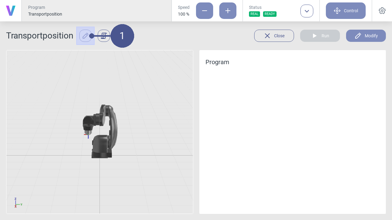
Fig. 31 Edit program
To edit a program, click on the pencil icon next to the program name (Fig. 31/➊).
Enter a new name or change the program description if needed.
Note
The pop-up menu opens (Fig. 32).
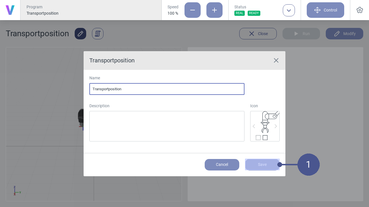
Fig. 32 Save program changes
Click Save to save the changes (Fig. 32/➊).
Note
The program can also be edited by clicking on the icon next to the program name in the pop-up window within the home screen.
2.2.9. Move robot manually
Warning
Risk of injury due to manual movement of the robot!
When moving the robot manually, there is a possibility that the robot is moved in an unsafe environment without prior risk assessment. In the event of physical contact, injuries may occur due to improper manual operation of the robot.
Ensure that the robot is only moved manually by the responsible system integrator.
Ensure that no unauthorized persons are in the working and danger area of the robot.
Ensure that no pointed or sharp-edged tools or devices are mounted to the robot.
Personnel: System integrator
Requirements
The robot is in manual operating mode.
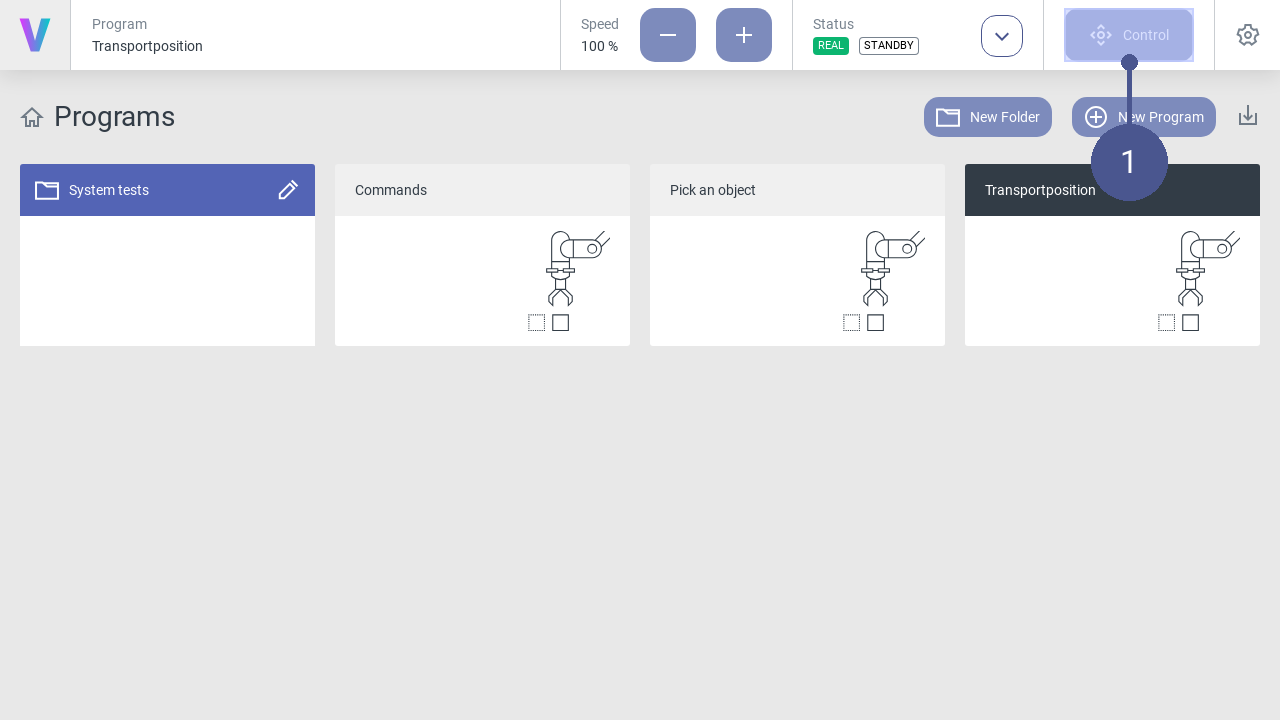
Fig. 33 Open control panel
Click Control in the navigation bar (Fig. 33/➊).
Note
The control menu opens (Fig. 34).
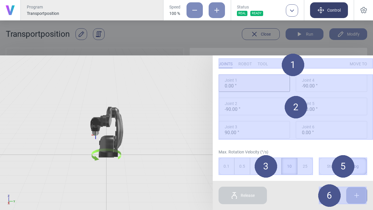
Fig. 34 Control panel
Select the desired coordinate system from the tabs (Fig. 34/➊).
Select the axis for which a movement is to be executed (Fig. 34/➋).
Select the jogging method (Fig. 34/➎):
- Step (Step-Jogging)
The robot moves step by step along the selected axis.
- Jog (Jogging)
The robot moves continuously along the selected axis.
Select angle length and angular velocity (Fig. 34/➌).
Click the plus or minus button to move the robot forward or backward along the selected axis (Fig. 34/➏).
Note
Move robot
Press and hold the plus or minus button to move the robot in a continuous motion while jogging.
To open or close the gripper unit connected to the media flange, click Open or Close (Fig. 34/➍).
Move robot to input pose
The robot can be manually moved to a specific target pose. Therefor, the target pose needs to be entered into the input fields.
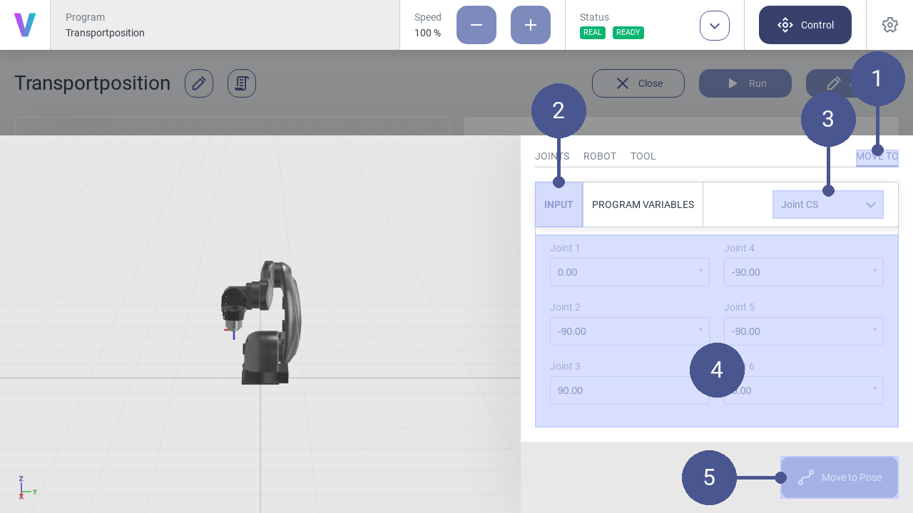
Fig. 35 Input pose
Open the control panel.
Navigate to MOVE TO (Fig. 35/➊) and select INPUT (Fig. 35/➋).
Select the coordinate system of the target pose (Fig. 35/➌).
Enter the target pose in the input fields (Fig. 35/➍).
Press and hold the Move to Pose button until the target pose is reached (Fig. 35/➎).
The robot is now at the target pose.
Move robot to program variable
The robot can be manually moved to a specific program pose variable. Therefor, the program variable needs to be selected first.
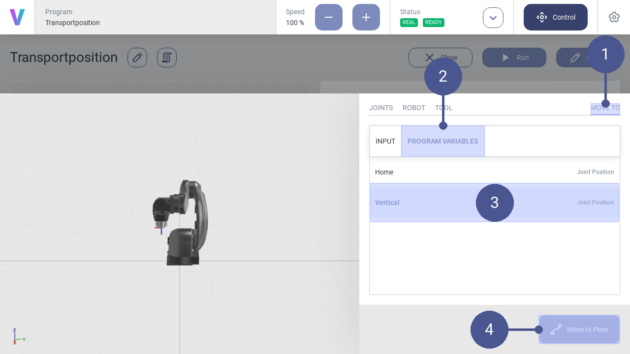
Fig. 36 Program variables
2.2.10. Reset system after software failure
The following section describes how to restart the robot after an emergency stop or after a change of the operating state.
Reset software failures.
Personnel: Operator
A software error can, for example, be triggered by system errors or incorrect movement of the robot.
When a system error is triggered, a notification appears in the status bar (Fig. 37/➊) and the error message is displayed in the notification bar (Fig. 37/➋).
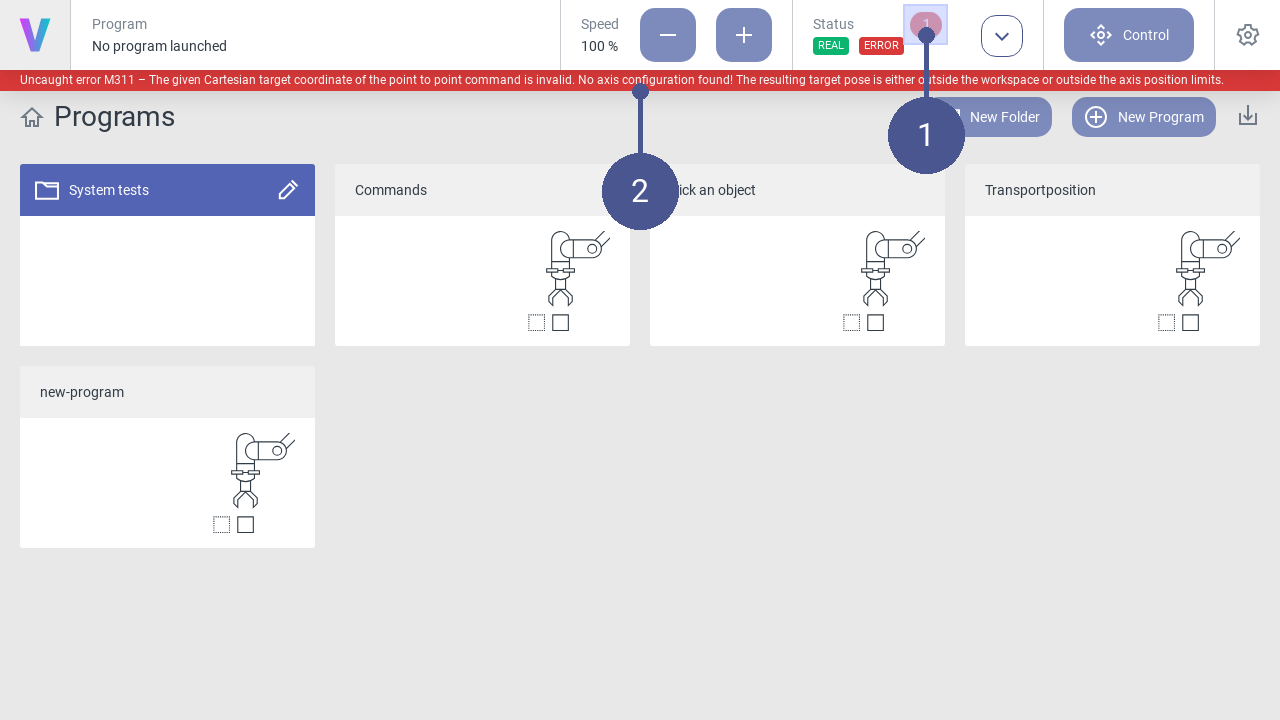
Fig. 37 Note error message
Open the status page and view details of the error message in the log (Fig. 38/➊).
Click Reset (Fig. 38/➋). The robot is set back to the Standby status (Fig. 38/➌). This can take a few seconds.
The robot can then be switched on again (Fig. 38/➍).
Other errors may be triggered during the process. In this case, follow the instructions in the log.
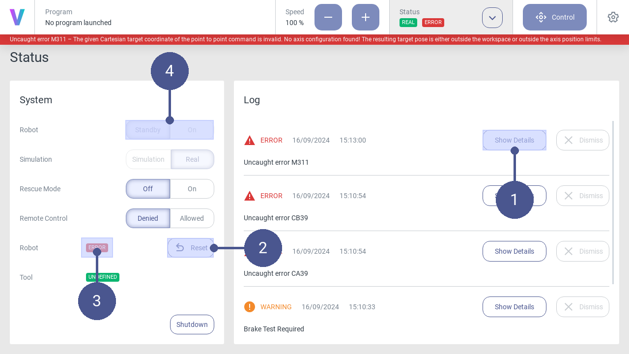
Fig. 38 Reset errors
2.2.11. Create a Move to command
Personnel: System integrator
Requirements
A new program has been created.
After creating a new program, the program editor opens automatically. Logic can be added to the program by adding individual commands via drag and drop or by clicking.
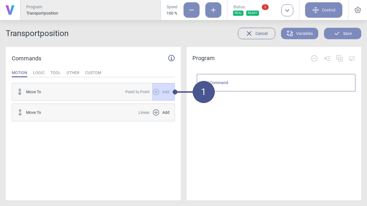
Fig. 39 Add command
Click the Add button of the Move to - Point to Point command in the program menu to open the window for a new motion command (Fig. 39/➊).
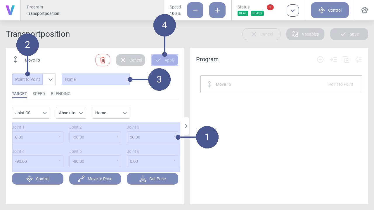
Fig. 40 Move-To command: Home position
Parameterize the motion command for the home position according to the values (Fig. 40/➊).
Make sure that the Point to Point entry is selected in the drop-down list (Fig. 40/➋). Individual adjustments are possible in the tabs.
Enter the name of the motion command (e.g. Home) (Fig. 40/➌).
Save the command with Apply (Fig. 40/➍).
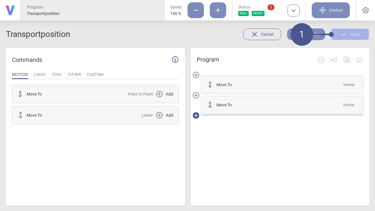
Fig. 41 Save program
When your program is final, click on the Save button (Fig. 41/➊).
The new program can be loaded and executed in the overview screen. Before running your program on a real robot, it’s possible to simulate your path with the digital twin first. To check and switch the mode, have a look on the status screen. While running the program a digital twin of the robot is shown.
Create variable of robot pose
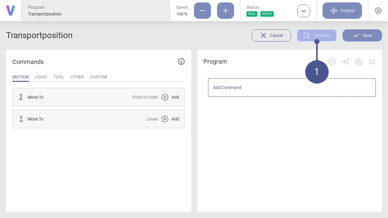
Fig. 42 Open variable manager
Click the Variables button in the program menu to open the window for managing and creating variables (Fig. 42/➊).
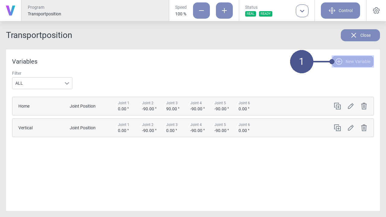
Fig. 43 Variable manager
On the variables page, click the New Variable button to create a new variable (Fig. 43/➊).
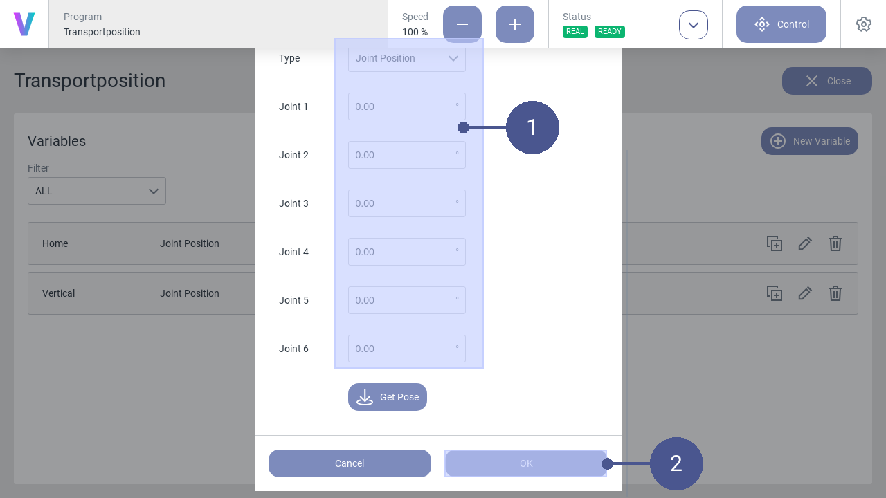
Fig. 44 Create variable
Select the Type Joint Position and parameterize the variable for the position (Fig. 44/➊).
Enter the name of the variable (e.g. Home).
Save the variable with OK (Fig. 44/➋)
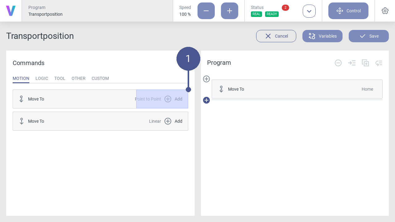
Fig. 45 Create position
Click on the Add button in the program menu to open the window for an additional motion command with the created variable (Fig. 45/➊).
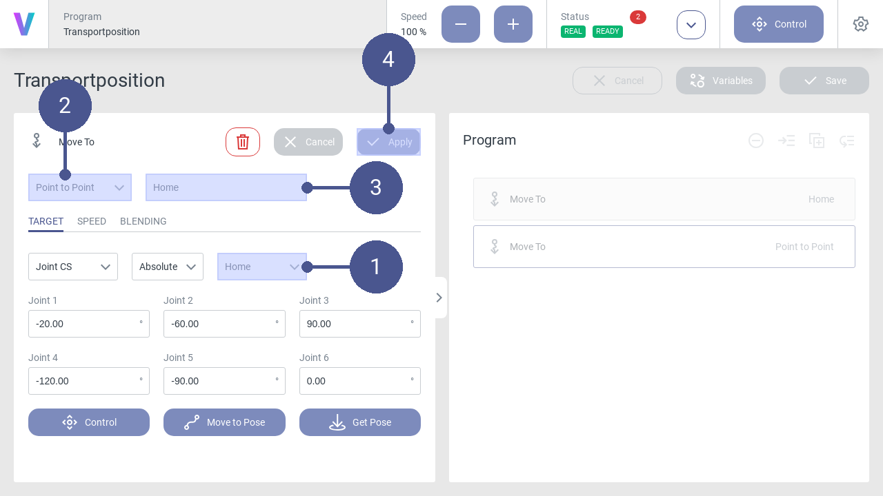
Fig. 46 Add variable
Use the drop-down list to select the variable Home (Fig. 46/➊). Afterwards the coordinates appear in the fields of the axes.
Make sure that the Point to Point entry is selected in the drop-down list (Fig. 46/➋).
Enter the name of the movement command (Fig. 46/➌).
Save movement command with Apply (Fig. 46/➍).
Fig. 47 Save transport position program
Click on the Save button (Fig. 47/➊).
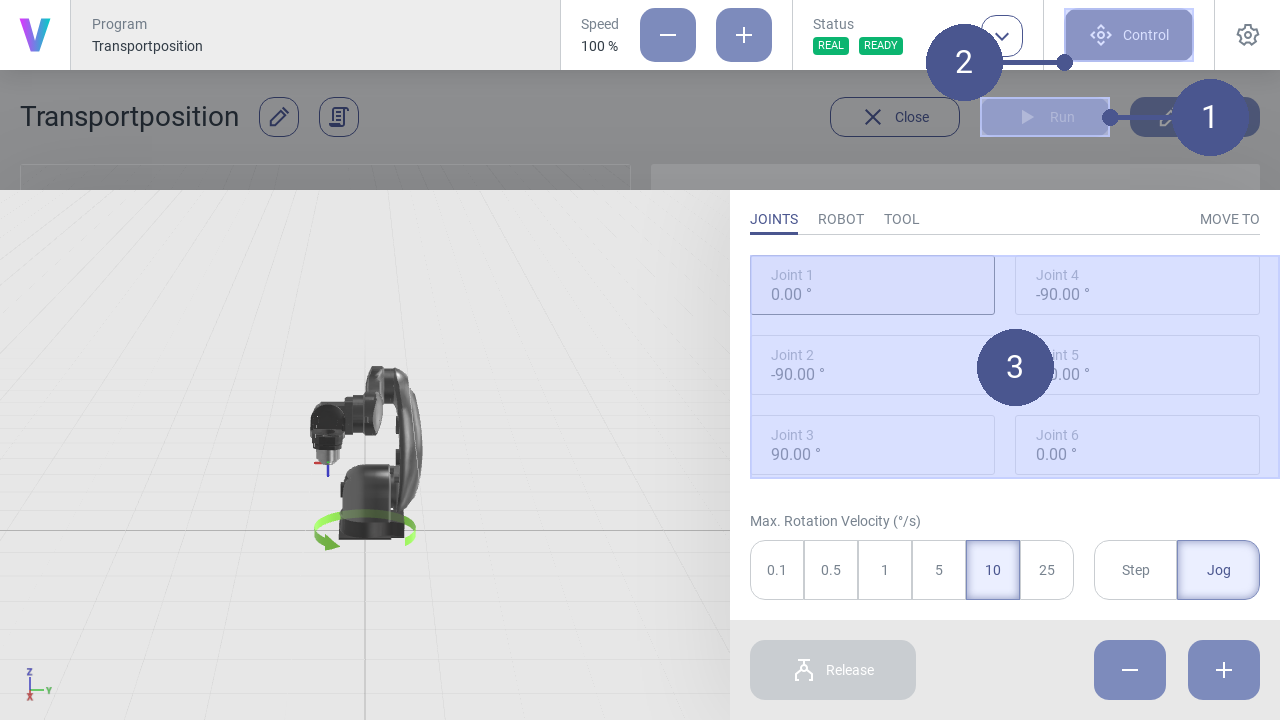
Fig. 48 Check transport position
2.2.12. Verify position
Personnel: Programmer, safety engineer, system integrator
If the robot has not been switched off properly (e.g., power supply to the robot controller has been interrupted), the reference position may be lost. In this case, the current position of the robot must be verified at the next restart. The pop-up window for position verification is automatically displayed in the user interface.
Requirements
The robot is in the manual operating mode.
No program is executed.
Remote Control
This chapter describes the usage of the external OPC UA interface to communicate with the robot. This server interface can be configured to fit to the needs of the use case regarding accessibility and security.
Information about data types and parameters will be set automatically from the original-source.
Note
The external OPC UA server can be reached via the robot’s IP address 192.168.1.1 with the port 4840.
2.2.13. Activate Remote Control
Personnel: System integrator
Warning
Risk of injury due to unexpected robot movement in remote mode!
When remote mode is active, the robot can be operated via an external remote control, e.g. in the form of a PLC. This means that a single point of control is no longer guaranteed and there is a possibility that robot movements are carried out from elsewhere (by people or machines). Before activating the remote mode, ensure:
The system integrator has identified the risks arising from remote access and taken them into account in his risk assessment of the robot application.
The system integrator has taken appropriate measures to minimize the risks.
The system integrator has actively enabled remote access.
There are no persons in the danger zone of the robot.
Functions in remote mode
The following robot functions are available in remote mode:
Start programs.
Stop programs.
Perform a reset of the robot.
Set digital outputs.
Requirements
No persons are in the danger zone of the robot.
Remote mode is enabled by the system integrator.
The robot is in the manual operating mode.
No program is being executed.
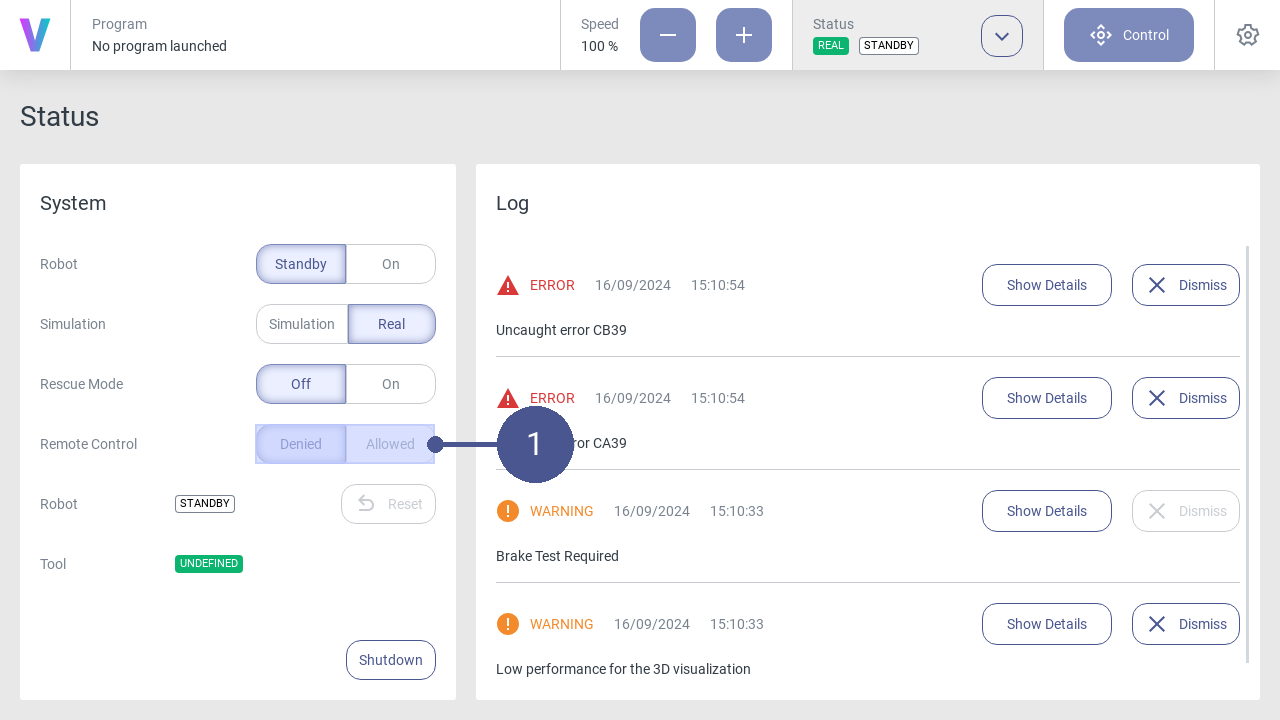
Fig. 49 Remote mode
Click on the Allowed button in the Remote control item in the status menu (Fig. 49/➊).
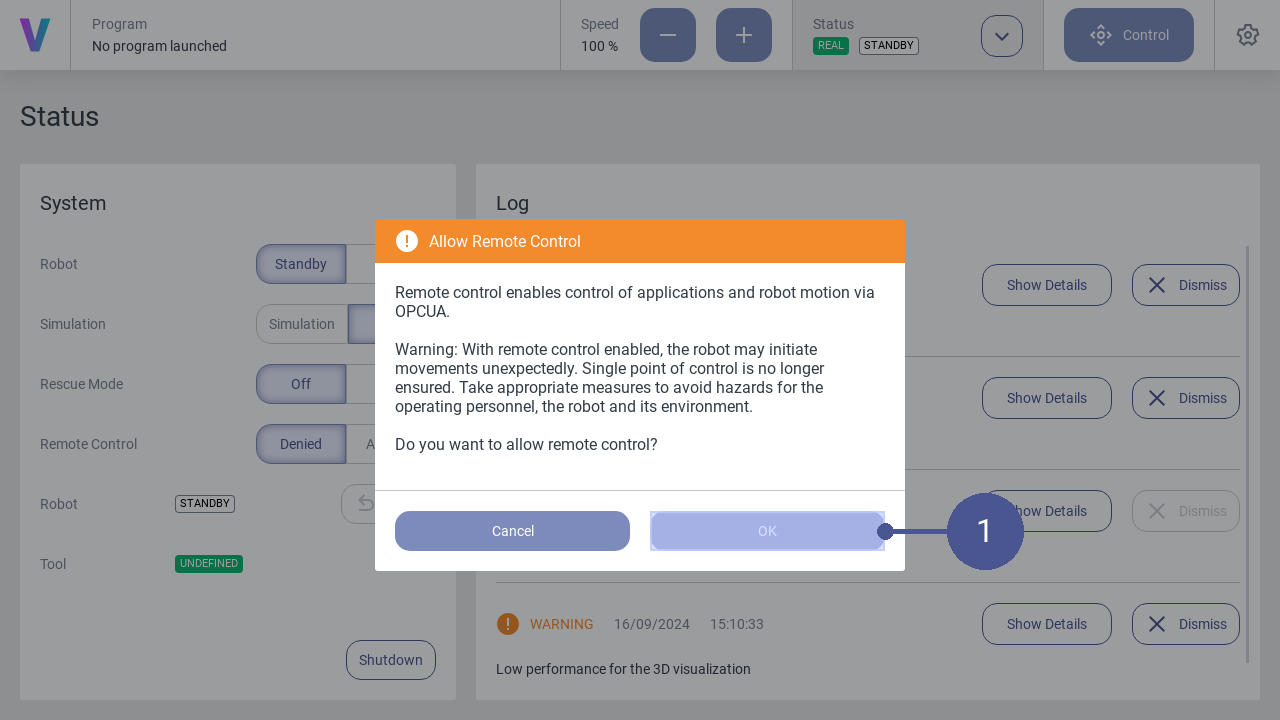
Fig. 50 Activate remote mode
Confirm with OK to activate the remote mode (Fig. 50/➊).
Fig. 51 Overview status badges
When the remote mode is active, the following icons are displayed in the user interface:
2.2.14. Configure the Remote Interface
The remote interface is an OPC UA interface and can be configured via a JSON file. It can be found on controller 2 at ~/config/ExternalOPCUA.Config.
Note
The external OPC UA server is automatically started with the system. Configuration changes will be applied with the next start of the system.
Header
Example of the minimal configuration of the configuration file. The name of the OPC UA server is set via ServerName to voraus_external in this example.
{
    "ExternalOPCUA": {
        "ServerName": "voraus_external",
        "MaxSessions": 10,
        "MaxSubscriptions": 25,
        "MaxMonitoredItems": 25,
        "MaxNodesPerRead": 25,
        "MaxNodesPerWrite": 25,
        "MinSamplingInterval": 200.0,
        "ChildGroups": [],
        "ChildNodes": []
    }
}
Object Nodes
Object nodes can be configured in ChildGroups. Object node have the following structure
{
    "NodeName": "Cabinet",
    "NodeDescription": "Inputs and Outputs from the Main Controller.",
    "ChildGroups": [],
    "ChildNodes": []
}
The NodeName is Cabinet and the description of this node is in NodeDescription. The object nodes can be added to other object nodes or to the root node, which is the header.
Variable Nodes
Variable nodes can be added in the ChildNodes. Variable nodes have the following structure
{
    "NodeName": "info1",
    "NodeID": 4011,
    "Server": "program"
    "ReadOnly": false
    "NodeDescription": "Info1 is the first variable of the program.",
}
NodeName is the displayed name. NodeIDis the source node id of the internal system and Server is the internal server on which the variable is available.
The attributes `ReadOnly` and `NodeDescription` are optional.
Method Nodes
- Method nodes can be added inside the ChildNodes. Method nodes have the following structure ::
{ “NodeName”: “Startprogram”, “NodeID”: 10067, “Server”: “SystemControl1” “NodeDescription”: “Set the digital output pin.”, }
NodeName is the displayed name. NodeIDis the source node id of the internal system and Server is the internal server on which the method is available.
2.2.15. How to use Remote Control
This tutorial describes how to use the external OPC UA server in combination with a program. It explaines how to exchange variables between the robot and an external device (e.g. a PLC) and to start and stop programs externally.
Create a new program or opening an existing one that you intend to use with the external OPC UA server.
Access the variables editor located in the top right corner and define the variables you wish to transmit. Supported data types include integer, float, and string.
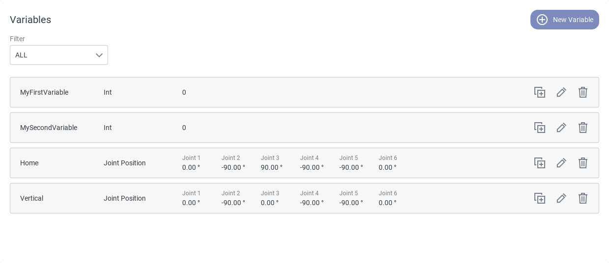
Fig. 52 Created variables
Note
The default values do not must be set. this is only for initializing them inside the program.
Define the program variables as OPC UA variables by inserting an OPCUA - Set Server Variable command for each variable at the start of your program. Enter the name of the variable into the text field for referencing. Select the appropriate variable type and enter the initial value.
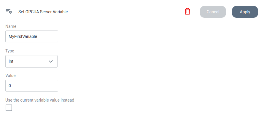
Fig. 53 OPC UA - Set Server Variable
Note
If the variable has previously been assigned a default value you want to keep, check the Use the current variable value instead checkbox. This feature can be utilized at any point within your program when transmitting the current variable value to an external device.
Define the variables in the config file of the external OPC UA server. It is not required for communication, but will produce more clarity on server side. Establish a connection to the voraus.core via SFTP or SSH and open the file ExternalOPCUA.Config. Locate the node program/AppSpecific, which contains default nodes named info1-5. Rename these nodes with your actual variable names, maintaining the same order as in the program.
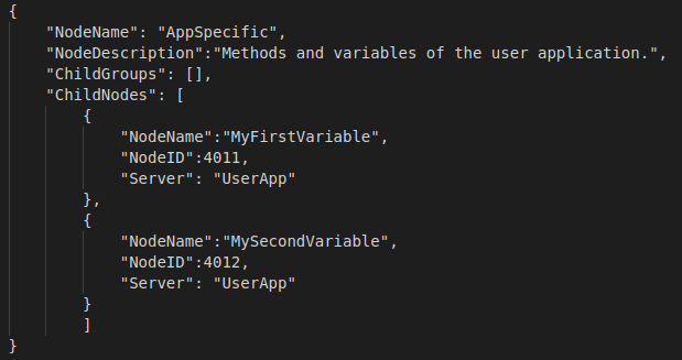
Fig. 54 Remote control config
Build the program like in the example below. Create a loop and add a OPCUA - Read Server Variable command for each of the variables you want to monitor inside your program. Enter the OPCUA variable name (defined by the OPCUA - Set Server Variable) command and the internal program variable name.
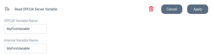
Fig. 55 OPC UA - Read Server Variable
Note
For best practice these should be called the same.
Each time the loop starts again, the current variable values from the external device will be written to your program variables and can be used inside the program. The displayed group command Do Something can be anything you want the robot to do. If you want to send a variable to the external device, use the OPCUA - Set Server Variable command and either enter a value or select the current variable value.
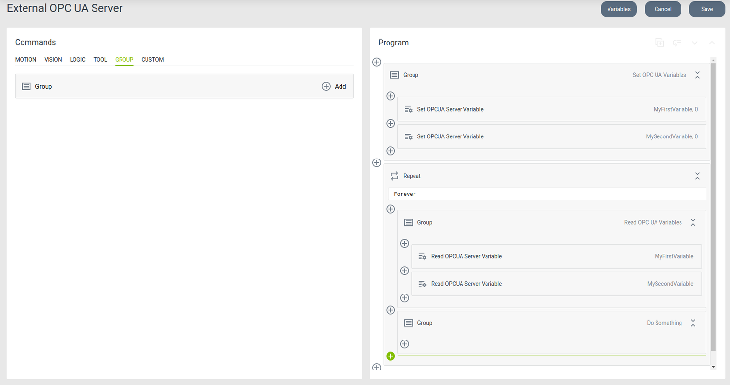
Fig. 56 Example program
Test your program with an external OPC UA client such es UaExpert. Establish a connection to the external OPC UA server (192.168.1.1:4840) and navigate to the node program/AppSpecific. Here, you can observe the variables from the ExternalOPCUA.Config file while the program is running. Drag them into the Data Access View to monitor their values. Additionally, you can set specific values that will be directly sent to your program.
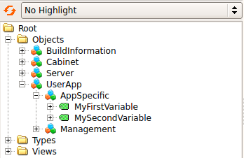
Fig. 57 Nodes in UaExpert