4. Commands
4.1. Motion
4.1.1. Move To Point-to-Point
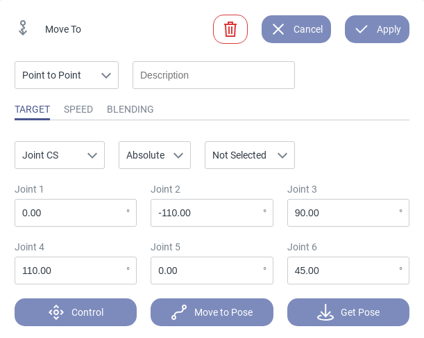
Fig. 67 Interface of the Move To PTP command
Description
Use this command to move the robot to the given target pose in the quickest way possible via a joint space movement. You can define the target coordinate system, choose between an absolute and a relative movement, set the movement speed and include a blending option.
This command moves the robot on a joint space path to the given target pose by synchronizing the motion of all axes to the slowest one. The resulting path is not always trivial and should therefore be tested with reduced speed to avoid collisions. If required, further way points can be added using additional Move To Point-to-Point commands with blending.
Parameterization
Movement type: Selection of the movement type (linear or point-to-point).
Description: Assign a name to the command which will be shown in the program overview.
Target: Coordinates of the commanded target pose in the selected coordinate system. If the target pose is given in a Cartesian reference frame, the solution of the inverse kinematics is not unique (i.e. there exists more than one possible valid axis configuration). In this case the robot will automatically determine a reasonable target configuration in joint space. If possible the one with the minimal moving distance for each joint.
Coordinate system: Define the reference frame in which the target pose is given. Options are: Joint CS, Robot CS, Tool CS and User CS.
Absolute/Relative: Specify whether the target is given as an absolute or a relative pose (added to the current pose).
Pose: Choose a pose from the existing program variables.
Speed: Change the velocity scaling in percent with respect to the maximum axis velocities. Whether the maximum velocity can be reached depends on the distance, the system’s dynamics limitations and the maximum Cartesian velocity.
Blending: Change the blending setting. Blending is parameterized retroactively. This means, the blending parameters of a segment define the transition of the parameterized segment with the previous segment. The value is given in percent and 100 percent blending corresponds to half of the angular movement of each motor. If the second motion segment is commanded with a delay (e.g. due to a condition), the blending might not be executed properly. PTP movements can be blended to avoid standstill and optimize traveling time.
Note
Blending between joint space and Cartesian movements is currently not supported.
Additional Information
Clicking the delete icon
 deletes the command.
The Cancel button closes the command editor without saving current changes.
The Apply button saves all current changes and closes the command editor.
Clicking the extended settings page icon
 on the right extends the page to show the digital twin or
the camera image.
on the right extends the page to show the digital twin or
the camera image.The Control button opens the control panel in which you can manually move the robot.
The Move to Pose button moves the robot to the pose entered in the input fields above.
The Get Pose button updates the entered coordinates with the robot’s current pose.
Applications
Reach a target pose the quickest way possible (e.g. to position the robot before executing a precision movement).
Avoiding obstacles within the robot’s workspace.
Traverse through singularities / change the robot’s axis configuration.
4.1.2. Move To Linear
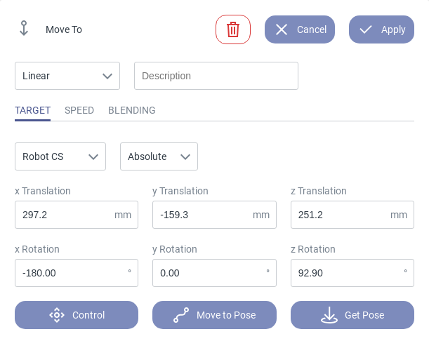
Fig. 68 Interface of the Move To Linear command
Description
Use this command to move the robot on a linear path to the given target pose. You can define the target coordinate system, choose between an absolute and a relative movement, set the movement speed and include a blending option.
Parameterization
Movement type: Selection of the movement type (linear or point-to-point).
Description: Assign a name to the command which will be shown in the program overview.
Target: Coordinates of the commanded target pose in the selected coordinate system. If the target pose is given in joint coordinates, the motion planner will determine the corresponding pose of the end effector based on the provided axis angles and use this Cartesian pose as target for the motion path. The robot will reach this Cartesian target pose but may not necessarily reach the parameterized joint configuration.
Coordinate system: Define the reference frame in which the target pose is given. Options are: Joint CS, Robot CS, Tool CS and User CS.
Absolute/Relative: Specify whether the target is given as an absolute or a relative pose (added to the current pose).
Pose: Choose a pose from the existing program variables.
Speed: Set the path acceleration and velocity or choose from presets. Whether the specified velocity can be reached during the particular motion command depends on the path geometry and the system’s dynamics limitations.
Blending: Change the blending setting. Blending is parameterized retroactively. This means, the blending parameters of a segment define the transition of the parameterized segment with the previous segment. The value is given in percent and 100 percent blending corresponds to half of the absolute length of the shorter one of both segments. If the second motion segment is commanded with a delay (e.g. due to a condition), the blending might not be executed properly. Linear movements can be blended to avoid standstill and optimize traveling time.
Note
Blending between joint space and Cartesian movements is currently not supported.
Additional Information
Clicking the delete icon
deletes the command.The Cancel button closes the command editor without saving current changes.
The Apply button saves all current changes and closes the command editor.
Clicking the extended page icon
on the right extends the page to show the digital twin or the
camera image.The Control button opens the control panel in which you can manually move the robot.
The Move to Pose button moves the robot to the pose entered in the input fields above.
The Get Pose button updates the entered coordinates with the robot’s current pose.
Avoid singularities, which might occur between the two points. Singularities are configurations in which the robot’s movement is blocked in certain directions. They are a mathematical property of the system and therefore only exist for Cartesian and not for joint movements. The velocity of Cartesian movements around singularities will be reduced the closer the respective singularity is.
Applications
Define a straight movement path between two points.
Approach a target point from an exactly defined direction.
4.1.3. Move Circular
Description
The Move Circular command can be used to move the robot on a circular path.
Parameterization
Summary: Three different types of circle parametrization are available. The command allows to specify the circle segment, the rotation direction, the rotation type and the type of orientation interpolation. Futhermore, one can activate blending with different parametrizations and set the movement parameters such as velocity and acceleration.
The following circle parameterizations are available.
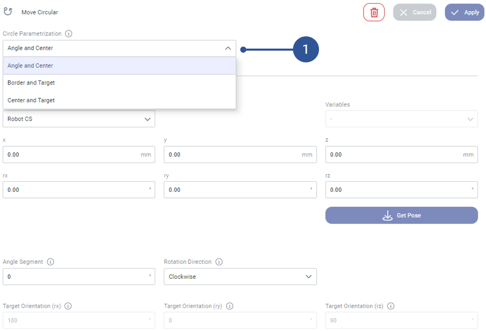
Fig. 69 Circle parameterization options
Angle and Center (Fig. 69/➊): Use this option to define the circle arc by the center point, the segment angle and the rotation direction. The rotation axis is defined by the center pose.
Border and Target (Fig. 69/➊): Use this option to define the circle arc by three points: The start point (current robot pose), an intermediate point on the circle (border point) and the target point.
Center and Target (Fig. 69/➊): Use this option to define the circle arc by the start point (current robot pose), the center point and the target point.
Angle and Center
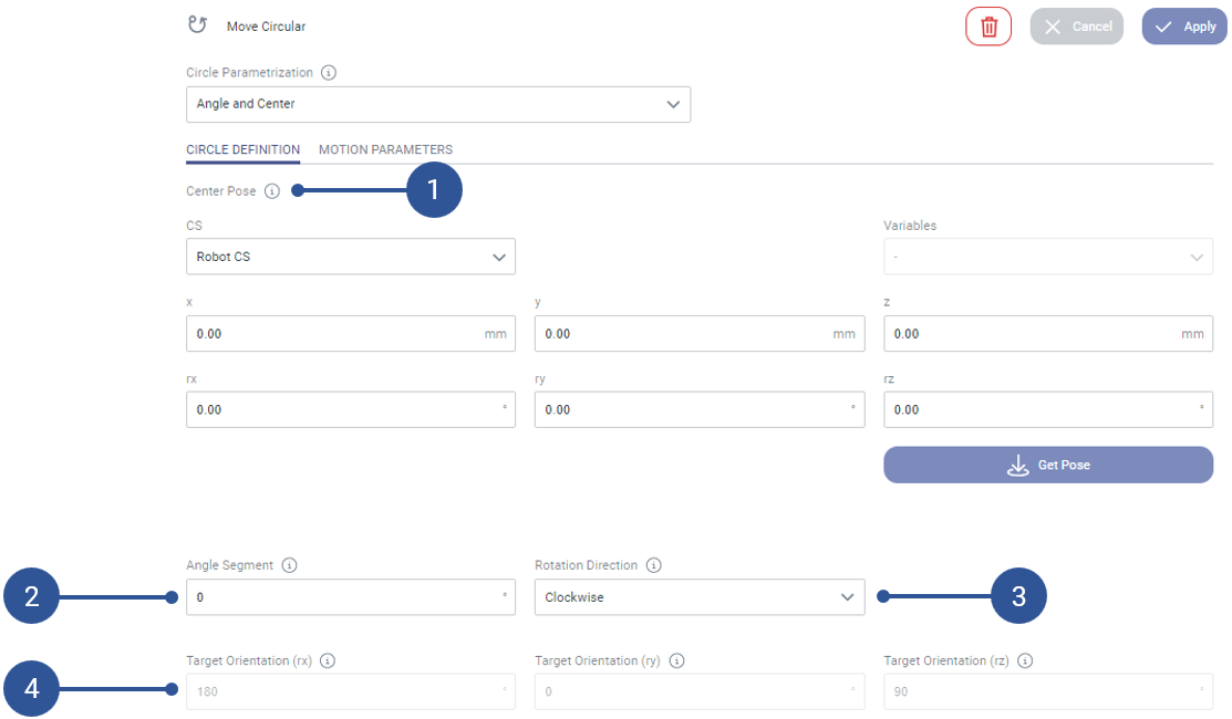
Fig. 70 Circle parameterization option: Angle and Center
Center Pose (Fig. 70/➊): Defines the center of the circle. The circle plane will be orthogonal to the center pose.
Angle Segment (Fig. 70/➋): Defines the angle of the circle segment. The input angle must be positive.
Rotation Direction (Fig. 70/➌): Defines the direction of the circular path. Options are: Clockwise and counterclockwise.
Target Orientation (rx) (Fig. 70/➍): Defines the x component of the target orientation (only if the orientation interpolation is set to simple).
Target Orientation (ry) (Fig. 70/➍): Defines the y component of the target orientation (only if the orientation interpolation is set to simple).
Target Orientation (rz) (Fig. 70/➍): Defines the z component of the target orientation (only if the orientation interpolation is set to simple).
Border and Target
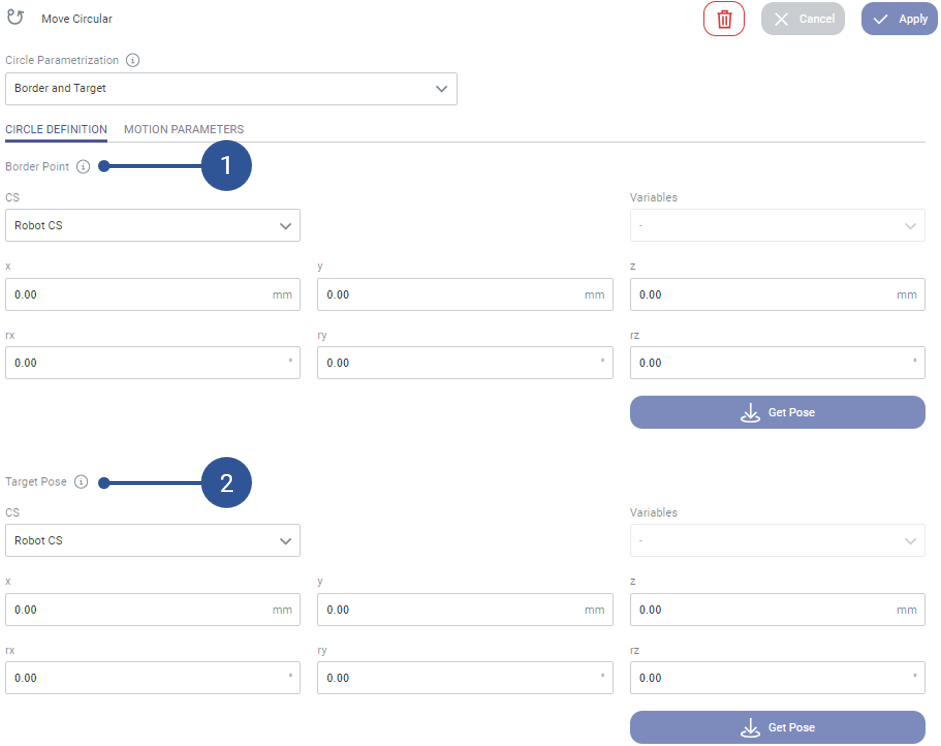
Fig. 71 Circle parameterization option: Border and Target
Border Point (Fig. 71/➊): Defines a via point on the circle. The orientation will not be considered.
Target Pose (Fig. 71/➋): Defines the target pose. The target orientation will only be considered if the orientation interpolation is set to simple.
Center and Target
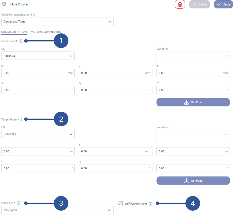
Fig. 72 Circle parameterization option: Center and Target
Center Point (Fig. 72/➊): Defines the center point of the circle. The orientation will not be considered.
Target Pose (Fig. 72/➋): Defines the target pose. The target orientation will only be considered if the orientation interpolation is set to simple.
Circle Path (Fig. 72/➌): Defines whether the robot will reach the target pose via the longer or the shorter circle path (clockwise or counterclockwise depending on the definition of the circle).
Shift Center Point (Fig. 72/➍): The center point will be shifted minimally within the circle plane so that an exact circle is defined by the start point, center point and target point. The target pose will be reached exactly as specified.
Motion Parameters
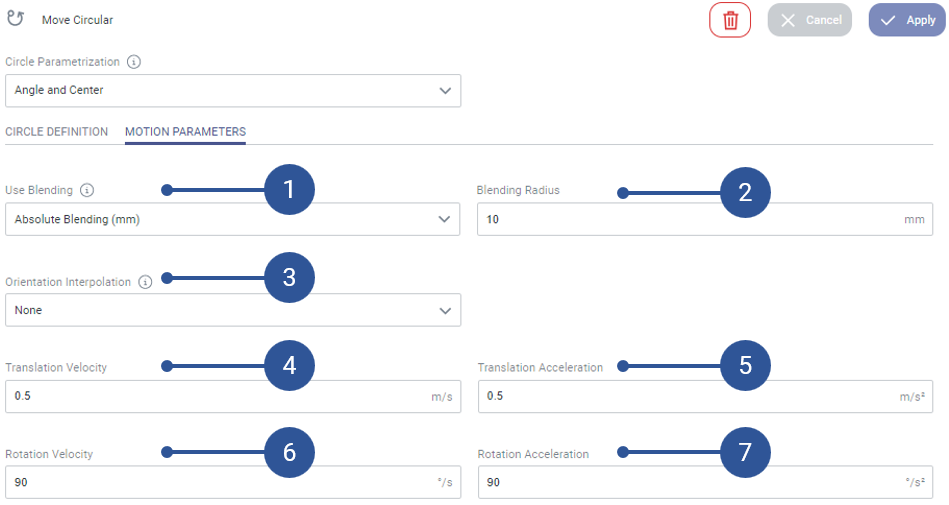
Fig. 73 Motion parameters for move circular command
Use Blending (Fig. 73/➊): Defines if the blending is active and selects between absolute and relative parameterization of the blending radius. Options are None, Absolute (mm) and Relative (%).
Blending Radius (Fig. 73/➋): Defines the blending radius. The unit is either Millimeter or Percent, depending on the selection of the Use Blending parameter.
Orientation Interpolation (Fig. 73/➌): Defines the rotation of the end effector during the movement. Options are: None, Simple, Constant to path.
Translation Velocity (Fig. 73/➍): Defines the velocity of the translational movement.
Translation Acceleration (Fig. 73/➎): Defines the acceleration of the translational movement.
Rotation Velocity (Fig. 73/➏): Defines the velocity of the rotational movement.
Rotation Acceleration (Fig. 73/➐): Defines the acceleration of the rotational movement.
Additional Information
The Angle and Center option can be used for circular movements with a circular angle of more than 360°.
Limitations
All points are defined with reference to the Robot CS.
The rotation type ‘Constant to path’ might not work at high speeds with big rotation angles due to velocity limitations of the axes. Try decreasing the translational velocity in this case.
The circle points (start-border-target and start-center-target) must not lie on a straight line since in the former case the circle radius would be infinitely big and in the latter case the circle plane cannot be identified unambiguously.
Applications
Move around a circle or around parts of a circle.
4.2. Logic
4.2.1. Conditional
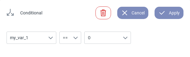
Fig. 74 Interface of the Conditional command
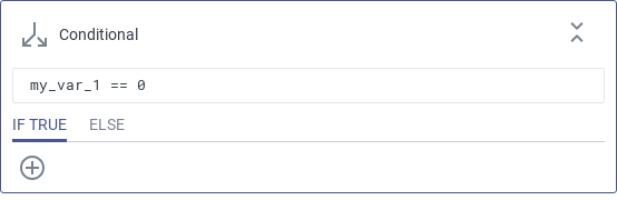
Fig. 75 Programming interface of the Conditional command
Description
Use this command to create a program branch that is only executed if a specified condition is satisfied (Fig. 75). If the condition is not satisfied the ELSE branch is executed.
Parameterization
Possible Conditions:
Tool State |
Compare the state of the equipped tool. |
Digital Input |
High/Low. |
Digital Output |
High/Low. |
Custom Variables |
Compare the value of a program variable. |
Additional Information
Available operators are:
equal to |
== |
not equal to |
!= |
less than |
< |
less than or equal to |
<= |
greater than |
> |
greater than or equal to |
>= |
Clicking the delete icon
deletes the command.
Applications
Integrate additional hardware (e.g. sensors) and trigger different actions depending on their state.
Check the tool state to ensure that an object has been grasped.
4.2.2. Repeat
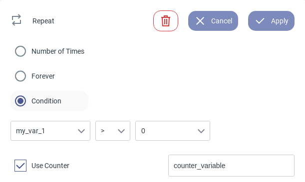
Fig. 76 Interface of the Repeat command
Description
Use this command to execute a group of commands in a loop. Choose between different conditions to end the loop.
Parameterization
Possible options:
Number of Times: Specify the number of repetitions by entering any positive integer.
Forever: Repeat the commands inside the group in an infinite loop.
Condition: Specify a condition. The internal commands will be repeated as long as the given condition holds true.
Use Counter [optional]: Create a counter variable which will be incremented with each repetition.
Counter Variable Example
In this example the counter variable is used to increase a different variable each 6th loop.
if (counter_variable % 6) == 0:
   tray_counter += 1
Additional Information
Clicking the delete icon
deletes the command.Digital inputs can be used as condition variable to react to states of external logical devices.
Applications
Automate repeating task without programming every iteration manually.
Execute a program in an infinite loop.
4.2.3. Set Digital Outputs
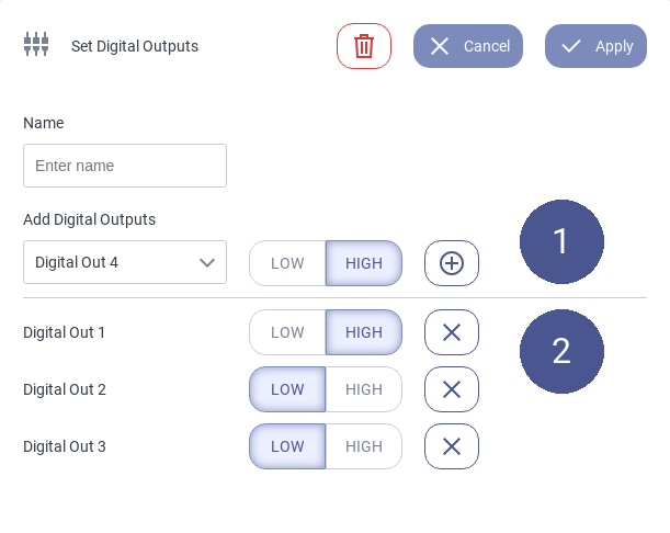
Fig. 77 Interface of the Set Digital Outputs command
Description
Use this command to set multiple digital outputs.
Parameterization
Name: Assign a name which will be shown next to the command.
Add Digital Outputs: Configure an output by selecting one from the dropdown menu and choosing LOW or HIGH. Click the add icon (Fig. 77/➊)
After adding an output to the configured outputs, you can change its state or delete it from the list by clicking on the corresponding delete icon (Fig. 77/➋).
Additional Information
Clicking the delete icon
deletes the command.
Applications
Control third party devices such as conveyor belts or status lights.
4.2.4. Set User CS
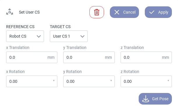
Fig. 78 Interface of the Set User CS command
Description
Use this command to create a new coordinate system which can be used for motion commands as a reference system. New coordinate systems must be defined with respect to other coordinate systems, e.g. the Robot CS.
Parameterization
Reference CS: Choose the coordinate system in which the user coordinate system is defined. Options are: Robot CS, Tool CS, User CS [1-4], Object CS and Tag CS.
Target CS: Select the User CS to be defined. Options are User CS [1-4].
x: x-coordinate of the origin w.r.t. the reference CS.
y: y-coordinate of the origin w.r.t. the reference CS.
z: z-coordinate of the origin w.r.t. the reference CS.
x-Rotation: Relative orientation around the x-axis w.r.t. the reference CS.
y-Rotation: Relative orientation around the y’-axis w.r.t. the reference CS.
z-Rotation: Relative orientation around the z’’-axis w.r.t. the reference CS.
Additional Information
Clicking the delete icon
deletes the command.The Get Pose button updates the entered coordinates with the robot’s current pose.
The relative orientation of the desired coordinate system is defined in Cardan angles, i.e. sequential (intrinsic) rotations around the x-axis, the rotated y’-axis, and the rotated z’’-axis of the reference CS.
Applications
Define a machine coordinate system in machine tending applications.
Define a tray coordinate system for (de-)palletizing tasks.
Limitations
The User CS is static. This command does not allow conveyor tracking etc.
4.2.5. Run Script
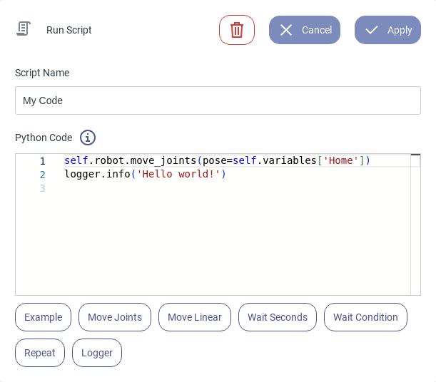
Fig. 79 Interface of the Run Script command
Description
Use this command to write custom Python code inside your program and create new functionalities.
Parameterization
Script Name: Assign a name to the command to describe its functionality.
Python Code: Use this editor to write your own Python code.
Additional Information
Import Python libraries to access various functionalities.
Clicking the delete icon
deletes the command.Clicking the info icon
 opens the Python robot API documentation for additional help.
Use the code snippets below the editor for syntax tips.
The Run Script command can be expanded in the program overview to show the Python code during program execution.
4.2.6. Wait
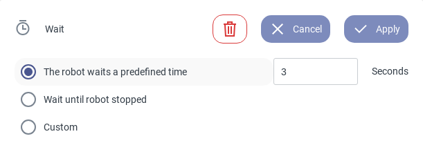
Fig. 80 Interface of the Wait command
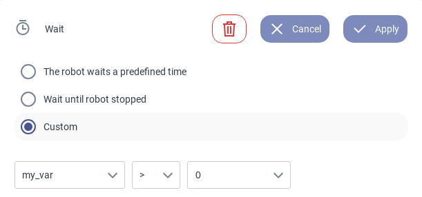
Fig. 81 Custom waiting condition
Description
Use this command to pause the program until a specified condition is met.
Parameterization
Wait time: Set the waiting duration in seconds.
Wait until robot stopped: The program pauses until the robot has stopped moving.
Custom: Define a custom condition. Options are: Tool state, Digital input, Digital output, program variables (see Fig. 81).
Additional Information
Clicking the delete icon
deletes the command.The custom variable can also be a loop counter from a previous Repeat command.
Available operators are:
equal to |
== |
not equal to |
!= |
less than |
< |
less than or equal to |
<= |
greater than |
> |
greater than or equal to |
>= |
4.3. Tool
4.3.1. Tool Command
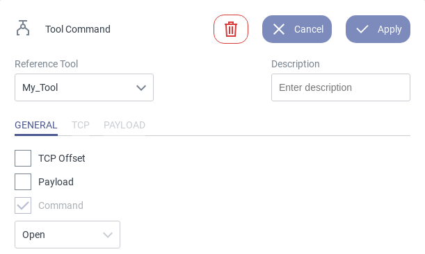
Fig. 82 Interface of the Tool Command
Description
Use this command to control the equipped tool and set a TCP and/or mass offset.
Parameterization
General
TCP Offset: Enable/Disable the TCP offset option.
Payload: Enable/Disable the payload option.
Command checkbox: Enable/Disable the tool command option.
Command dropdown: Select a tool command from the dropdown menu. Available options depend on the active tool. New commands can be added via the tool settings.
TCP
Payload
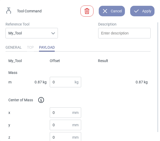
Fig. 83 Defining a payload
Clicking the delete icon
deletes the command.Only the differences in position/orientation/mass have to be specified. The resulting values will be shown in the interface.
The new TCP and payload parameters will be considered in the robot’s dynamics and kinematics model.
The code generator will automatically insert a wait_for_robot_stop_movement() command before the tool command, hence the tool command will only be executed after the robot has come to stop. If you want to control the tool during the robot’s movement, use the execute_tool_command() command via Python.
Applications
Control the tool (e.g. a gripper) to handle objects in pick-and-place applications, etc.
Adjust the TCP and payload parameters when an additional tool and/or heavy object has been grasped.
4.4. Other
4.4.1. Group

Fig. 84 Interface of the Group command
Description
Use this command to group multiple commands and assign a name to them. If necessary, the group can be collapsed to improve the program’s readability.
Parameterization
Group Name: Assign a name to the group to describe its functionality.
Additional Information
Clicking the delete icon
deletes the command.
Applications
Improve the program’s readability.
Group several commands that belong to one specific task (machine tending, part inspection, etc.).
4.5. Handling
4.5.1. Pick & Place
Description
The Pick Object command can be used to easily grasp an object via intermediate poses.
The Place Object command, on the other hand, can be used to easily place an object via intermediate poses.Note
Pick & Place
For simplicity reasons the Pick Object command and the Place Object command are from now on referred to as one command, named Pick & Place.
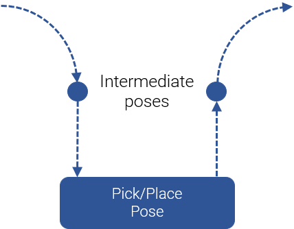
Fig. 85 Pick & Place command summary
Fig. 85 shows the different poses used by the Pick & Place command. The intermediate poses allow to move the robot quickly from one command to the next while at the same time avoiding collisions. Furthermore, to avoid collisions between the intermediate poses and the pick/place pose, the intermediate poses are often defined in such a way that the robot can be moved on a straight line going to and coming from the pick/place pose. Therefore, the Pick & Place command consist of the following sub-commands:
A PTP motion to the first intermediate pose.
A linear motion from the first intermediate pose to the pick/place pose.
A command to close (pick) or open (place) the tool.
A linear motion from the pick/place pose to the second intermediate pose.
Parameterization
Pick & Place pose
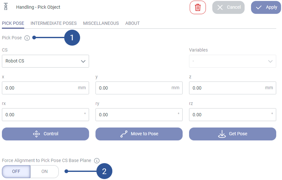
Fig. 86 The pick or place pose
Pick/Place pose (Fig. 86/➊): Pose at which the robot closes (pick) or opens (place) the tool and takes (pick) or puts (place) the object.
Force alignment (Fig. 86/➋): If activated, the rotation around rx and ry of the pick or place pose is ignored and the tool is aligned to the xy plane of the chosen coordinate system.
Intermediate poses
The intermediate poses are the poses to which the robot moves before and after the pick or place operation. The intermediate poses before and after a pick or place operation can (but do not have to) be the same . Fig. 87/➊ shows the different methods to define the intermediate poses.
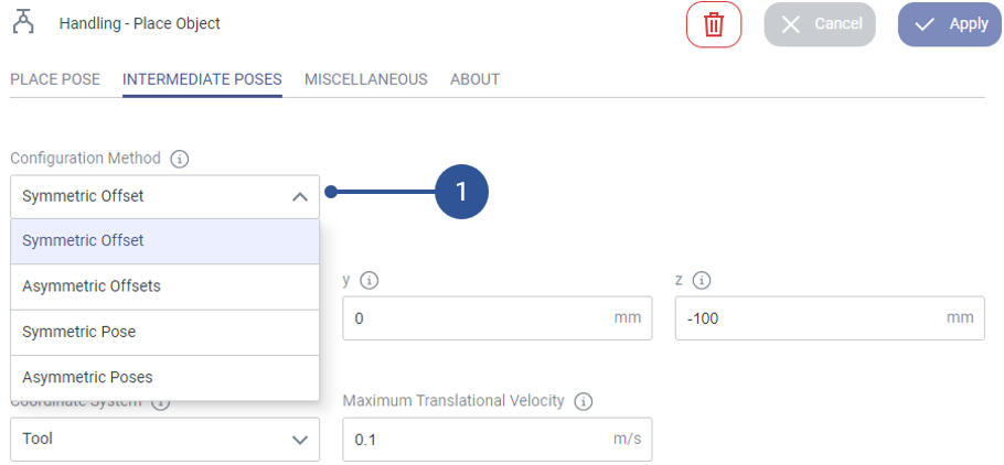
Fig. 87 The different methods to define the intermediate poses
Symmetric Offset
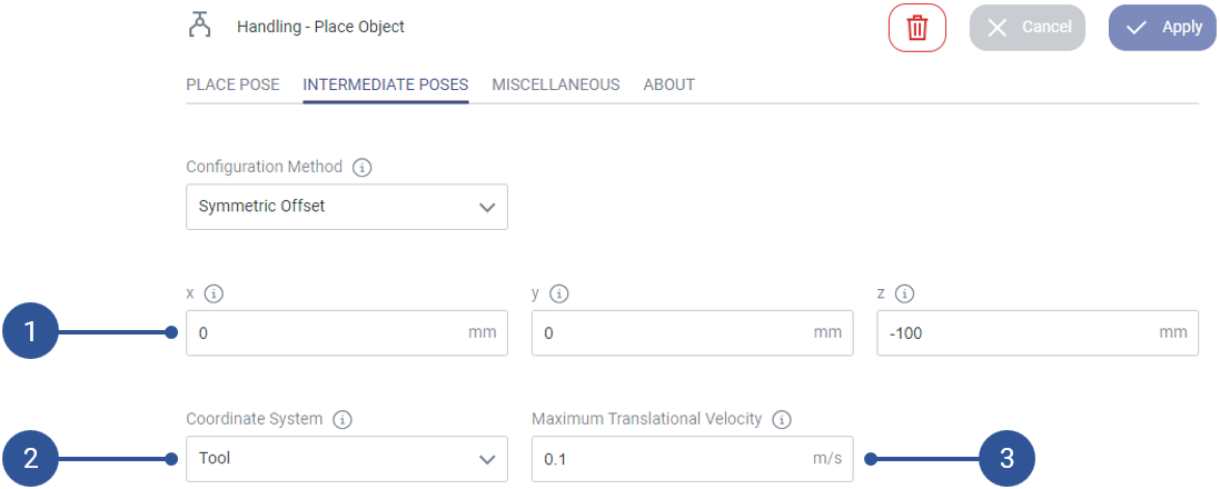
Fig. 88 The symmetric offset method
The symmetric offset method allows to define the intermediate poses via an offset relative to the pick or place pose (Fig. 88/➊). For the intermediate pose before and after the pick or place operation the same offset is used. The coordinate system in which the offset is defined can be freely chosen (Fig. 88/➋). Futhermore, the maximum velocity for the linear motion to and from the pick or place pose can be specified (Fig. 88/➌).
Asymmetric Offset
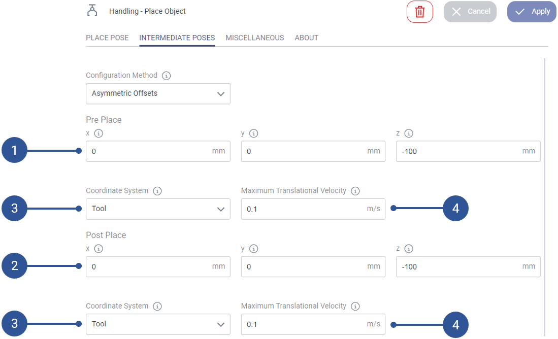
Fig. 89 The asymmetric offsets method
The asymmetric offset method allows to define the intermediate poses via offsets relative to the pick or place pose. For the intermediate poses before and after the pick or place operation a separate offsets can be defined (Fig. 89/➊ + ➋). The coordinate systems in which the offsets are defined can be separately chosen (Fig. 89/➌). Futhermore, the maximum velocities for the linear motions to and from the pick or place pose can be separately specified (Fig. 89/➍).
Symmetric Pose
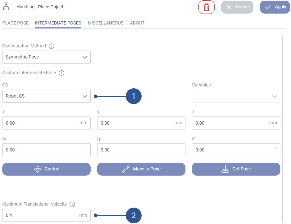
Fig. 90 The symmetric pose method
The symmetric pose method allows to define the intermediate poses via a custom pose (Fig. 90/➊). The custom pose is used for the intermediate pose before and after the pick or place operation. The coordinate system in which the custom pose is defined can be specified (Fig. 90/➋). Futhermore, the maximum velocity for the linear motions to and from the pick or place pose can be specified (Fig. 90/➌). The same velocity is used for the linear motion to and from the pick or place pose.
Asymmetric Poses
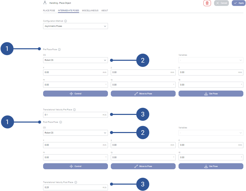
Fig. 91 The asymmetric poses method
The asymmetric poses method allows to define the intermediate poses via custom poses (Fig. 91/➊). The intermediate poses before and after the pick or place operation can be defined separately. The coordinate systems in which the custom poses are defined can be specified separately (Fig. 91/➋). Futhermore, the maximum velocities for the linear motions to and from the pick or place pose can be specified separately (Fig. 91/➌).
Miscellaneous
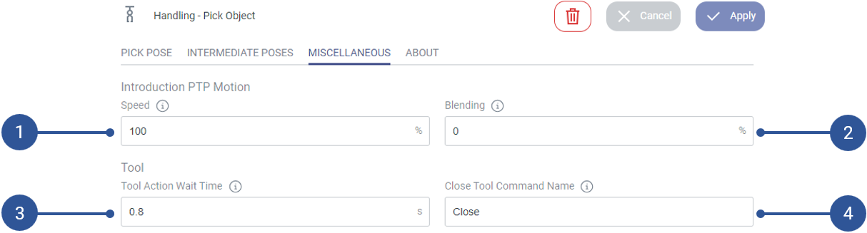
Fig. 92 Miscellaneous
PTP Motion - Speed (Fig. 92/➊): Defines the speed of the PTP motion to the first intermediate point.
PTP Motion - Blending (Fig. 92/➋): Defines the blending of the PTP motion to the first intermediate pose.
Tool - Wait time (Fig. 92/➌): Defines the time to wait for the tool to perform its closing (pick) or open (place) action.
Tool - Command name (Fig. 92/➍): Defines the name of the open/close command for the tool used.
Applications
Easily pick or place an object via intermediate points.