3.2. Overview of the Configurable Limitations
voraus Robot Control allows the configuration of various limitations to ensure that the robot operates safely and within the intended performance boundaries. These limitations define permissible ranges for axis-level and Cartesian movements as well as general robot parameters. The following section provides an overview of the available limit types and their influence on the robot behavior.
3.2.1. Limits
Limits are divided into different types. Depending on the type, a limit covers a scalar value (e.g., TCP velocity) or a vector of values (e.g., axes velocity). Limit values can be checked against reference values or are used in path planning and pre-interpolation.
The limit type also defines whether the limit value is set as an upper or lower limit.
For upper limits the reference value must not be greater than the limit.
For lower limits the reference value must not be less than the limit.
The following table shows a short overview of the existing limit types. Please note that axis torques also refer to axis forces when the joint is prismatic, even if the naming does not explicitly include the term “force”.
Limit Type |
Upper/Lower |
Size |
Unit |
Used for |
|---|---|---|---|---|
Axes acceleration |
UPPER |
For each axis |
rotational: \([\mathrm{rad/s^2}]\)
prismatic: \([\mathrm{m/s^2}]\)
|
|
Axes velocity |
UPPER |
For each axis |
rotational: \([\mathrm{rad/s}]\)
prismatic: \([\mathrm{m/s}]\)
|
|
Axes minimal position |
LOWER |
For each axis |
rotational: \([\mathrm{rad}]\)
prismatic: \([\mathrm{m}]\)
|
|
Axes maximal position |
UPPER |
For each axis |
rotational: \([\mathrm{rad}]\)
prismatic: \([\mathrm{m}]\)
|
|
Axes relative torque |
UPPER |
For each axis |
rotational: \([\mathrm{Nm}]\)
prismatic: \([\mathrm{N}]\)
|
Difference between measured and commanded torque on load side
|
Axes absolute torque |
UPPER |
For each axis |
rotational: \([\mathrm{Nm}]\)
prismatic: \([\mathrm{N}]\)
|
|
TCP translational velocity |
UPPER |
Scalar |
\([\mathrm{m/s}]\) |
|
TCP rotational velocity |
UPPER |
Scalar |
\([\mathrm{rad/s}]\) |
|
TCP measured force |
UPPER |
Scalar |
\([\mathrm{N}]\) |
|
Elbow translational velocity |
UPPER |
Scalar |
\([\mathrm{m/s}]\) |
|
Robot mechanical power |
UPPER |
Scalar |
\([\mathrm{W}]\) |
|
If a monitored limit is exceeded, the robot stops and an error is triggered.
Note
There is one exception to this:
Axes acceleration can be exceeded by a certain factor before an error is triggered.
Not all limits are supported by every robot. Some limits require additional sensors (e.g., for external forces and torque measurements) or a dynamic model to be configured.
Edge Cases and Known Limitations
This section describes specific situations that require special consideration when configuring and monitoring limits.
Unsupported Limit Types
Warning
Currently, no error is set if an unsupported limit type is used.
Very Low TCP Velocity Limits
Currently, when the user defines a very low TCP velocity limit (e.g., 100 mm/s), TCP velocity violations may occur during motion because the robot does not decelerate sufficiently to stay within the configured limit. No issues have been observed at velocity limits of 250 mm/s or above.
3.2.2. Limit Set
A limit set is a collection of several limits:
all limit types are available, but do not have to be specified.
unused limits are disabled by default and set to min/max values.
Limit sets represent various limiting sources. For example, restrictions based on the machine manufacturer’s
specifications or safety settings. Therefore, there are always the limit sets MACHINE and SAFETY.
MACHINE: From the robot config file, this is read and created during the startup process.SAFETY: Depending on the robot, this limit set results from the safety implementation.
It is also possible for users to define multiple limit sets themselves. These can be activated or deactivated by the user when the robot is in a standstill.
Limits within a limit set are only monitored if the limit set is active.
3.2.3. User defined limits
As mentioned before, the user can define limit sets themselves and save them as JSON file
under the following path: ${VORAUS_DATA_DIR}/userLimitSets/. We recommend choosing a file name that is identical
to the limit set name.
The user limit sets JSON files are read during the startup process of voraus Robot Control. Therefore, changes to the JSON files during runtime will only be applied on the next restart.
JSON File Definition for Limit sets
All values are defined in user friendly units as [m], [°], [Nm], or [N]. In the following sections the required and optional parameters of a limit set are described.
Required Parameter
Entry Name |
Unit |
Description |
|---|---|---|
|
string |
Limit set name, must be unique. |
|
bool |
Default activation state of the limit set at startup. Configured limits can only be monitored when the limit set is active. |
Optional Limit Parameter
Note
All limit parameters, which define the limit set, are optional.
Note
Currently all vector limits must have the size 6. We recommend to use high dummy values for unused axes.
Example for the usage in a JSON file
The following examples shows how the required parameters and all optional parameters can be used in a JSON file.
 1{
 2    "name": "MyLimit",
 3    "isActive": true,
 4    "axesAcceleration": [210.0, 210.0, 210.0, 210.0, 210.0, 210.0],
 5    "axesVelocity": [140.0, 140.0, 170.0, 180.0, 180.0, 180.0],
 6    "axesPositionMin": [-220.0, -310.0, -160.0, -310.0, -220.0, -360.0],
 7    "axesPositionMax": [220.0, 130.0, 160.0, 130.0, 220.0, 360.0],
 8    "axesTorqueRelative": [10.0, 10.0, 10.0, 5.0, 5.0, 5.0],
 9    "axesTorqueAbsolute": [200.0, 200.0, 200.0, 100.0, 100.0, 50.0],
10    "tcpVelocityTranslational": 2.0,
11    "tcpVelocityRotational": 360.0,
12    "robotPower": 5000
13}
In contrast to the previous cases, the following configuration example illustrates the structure of the JSON file where only a single parameter from the available optional parameter list is defined.
3.2.4. Limitation Handler
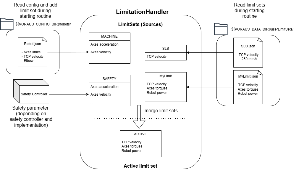
The LimitationHandler manages all defined limit sets. It can add, remove, and replace limit sets. It also calculates the resulting active limits.
The most restrictive limit for each limit type is determined from all active limit sets in each cycle, and set as the active limit. Active limits are published via OPC UA.
Example: Based on the two limit sets MyLimit and SLS from the previous section, the TCP
translational velocity is initially limited to \(2.0[\mathrm{m/s}]\).
Activating the limit set SLS reduces the limit to \(0.25[\mathrm{m/s}]\). TCP translational velocity is an
UPPER limit and the SLS limit value is smaller than that of MyLimit.
A schematic overview of this process can be seen in Fig. 2.
3.2.5. OPC UA
Under the node Robot/Limitations/ (NodeId: 100700) the following information is provided:
NodeId |
Name |
Description |
|---|---|---|
107100 |
ActiveLimits |
Overview of active limit values |
107200 |
ListOfLimitSets |
List of existing limit set names |
Commands to manage limit sets are located at Robot/Commands/Limitations/ (NodeId: 100701)
NodeId |
Name |
Description |
|---|---|---|
107102 |
ActivateUserLimitSet |
Activates an user defined limit set |
107103 |
DeactivateUserLimitSet |
Deactivates an user defined limit set |
107204 |
GetLimitSet |
Provides the values of a specific limit set |
A limit set can only be activated or deactivated when the robot is at a standstill. The robot must also not be in ACTIVE
or GRAVCOMP mode. MACHINE and SAFETY limit sets cannot be deactivated, as they are always activated.
Note
Changes made by these commands are not persistent. After the next restart, the values from the config files are restored.
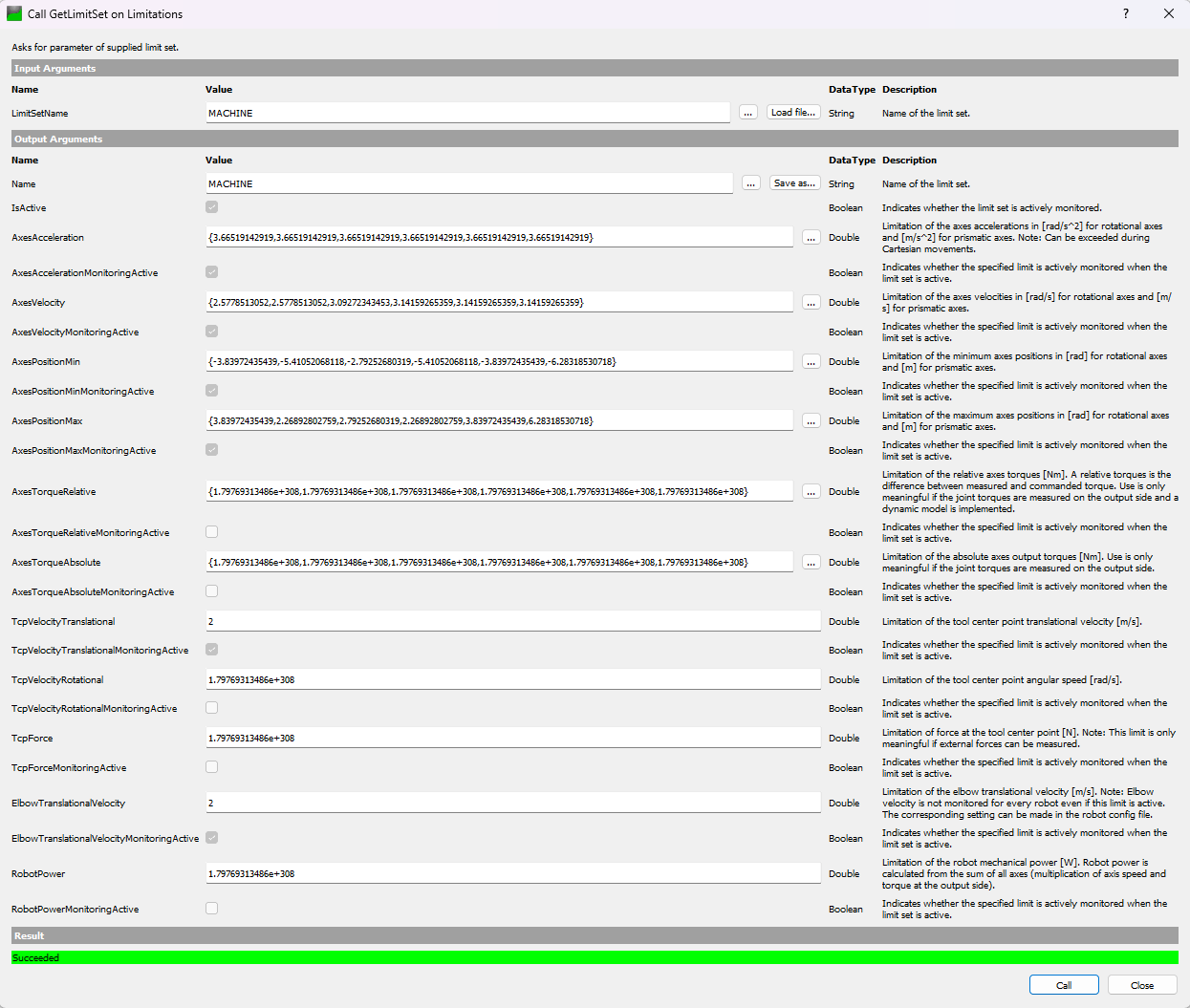
An example for the command Robot/Commands/Limitations/GetLimitSet is shown in figure
Fig. 3.