
6. Cyclic Position Commands
The cyclic position command interface enables real-time robot control by continuously transmitting position frames at a defined cycle time. It provides precise and smooth trajectory execution, especially for applications requiring high-frequency motion updates. Communication is handled via the OPC UA server of the voraus Robot Control, while an external OPC UA client maintains synchronization with the voraus Robot Control cycle. The following sections describe the requirements, execution sequence, and practical considerations for operating the cyclic position interface.
6.1. Client Requirements
It is recommended that the user employs a client capable of reliably transmitting new position commands within the cycle time of voraus Robot Control and therefore of the voraus.core. As mentioned in section Process Data the current cycle time can be viewed under NodeId: 100902 on the voraus Robot Control OPC UA server.
6.1.1. Non-Real-Time Clients
Non-real-time clients can compensate for timing delays by using the lookaheadFrames parameter
(see section Start Position Stream). However the use of lookaheadFrames causes the robot motion to start
with a delay which also depends on the cycle time resulting in increased latency.
Alternatively, frames can be intentionally skipped by sending only every n-th frame (see Fig. 28). However, linear approximation of missing frames can lead to deviations in the robot path as well as increased velocities and accelerations.
The permitted tolerance for lost or skipped frames, defined by the consecutiveFrameLossTolerance parameter,
can be configured in the StartPositionStream command.
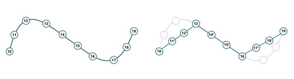
Fig. 28 Left: regularly planned trajectory; Right: trajectory with frame approximation (only every third frame is sent)
6.2. Trajectory Constraints
For the specified trajectory, it is essential that it remains continuous and free of discontinuities. The incoming trajectory is forwarded directly to the robot, without additional filtering, after being validated against the active robot limitations (see the following sections Start, Motion, and End). Therefore, it is strongly recommended that the trajectory be tested in advance to ensure stable robot motion and to avoid oscillations or instability.
In particular, trajectories containing approximated frames should be thoroughly tested and should not operate close to the maximum limitation values. It cannot be guaranteed that all limit conditions will be strictly maintained when linear approximation is applied.
6.2.1. Start
The cyclic position stream must be initiated while the robot is at a complete standstill and aligned with its current pose within the defined coordinate system.
6.2.2. Motion
During robot motion, both positional and velocity limits must be observed in joint space and Cartesian space:
6.2.3. End
The cyclic position stream must end in a stationary state:
6.3. Executing the Cyclic Position Stream
For cyclic position stream the voraus Robot Control provides the following methods within the OPC UA server:
StartPositionStreamSendNextCyclicPositionSendNextCyclicPositionBatchStopPositionStreamAbortPositionStream
A more detailed description of these methods can be found in the following section OPC UA Interface. The user requires an OPC UA client capable of connecting to the server of the voraus Robot Control.
6.3.1. Starting Position Stream
The cyclic position command sequence is initiated using the OPC UA command StartPositionStream, see also
section Start Position Stream.
The conditions required to start the cyclic position stream are as follows: the robot must be stationary,
the controllers must be switched on (READY), no motion commands (e.g., MoveLinear, MovePTP, MoveCircular, Jogging, etc.)
must be active or pending, and no other cyclic position command must already be running. The sections
Start and Initial Pose Requirements provide additional information about the
starting pose. When the position stream is started, a SessionToken is returned, which must be used for all
subsequent commands.
After sending the StartPositionStream command, it takes approximately three voraus cycles for the cyclic
position command to become active, which can be observed by the transition to the ACTIVE state. During this time,
no frames are extracted from the buffer or interpolated. voraus Robot Control expects new position commands cyclically.
6.3.2. Executing Position Stream
During the cyclic position command process the user can send new coordinates (referred to as frames) to voraus Robot
Control via the commands SendNextCyclicPosition and SendNextCyclicPositionBatch
(see section Send Next Cyclic Position). The latter allows sending multiple frames in one request, which can be
advantageous for reducing communication overhead and ensuring a more consistent stream of frames.
The cyclic interpolation of received frames requires that the cyclic position command has already been started using
the StartPositionStream command. New frames must be sent in a timely manner to ensure that there is always at
least one frame available in the buffer for interpolation.
The frequency of required frames depends on the cycle time of voraus Robot Control, with an average of one frame needed
per cycle. Multiple frames can be transmitted to voraus Robot Control per cycle, either via multiple
SendNextCyclicPosition commands or a single SendNextCyclicPositionBatch command.
There is a maximum number of frames that can be stored in the buffer
(see maxBufferSize in section Process Data).
Frames are added to the queue incrementally. When large batches are transmitted, multiple cycles may be required before
all frames are processed and reflected in Process Data.
The following points must also be considered:
Received frames are temporarily stored in an internal buffer within voraus Robot Control.
Each frame is assigned an incrementing
FrameCounter.Each
FrameCountervalue can only be sent once and cannot be overwritten afterward.Missing
FrameCountervalues are linearly approximated and automatically added to the buffer, provided that the difference to the next knownFrameCounterdoes not exceed theconsecutiveFrameLossToleranceparameter from theStartPositionStreamcommand. This can also be observed in Fig. 28.Approximated frames can still be replaced by a regular frame in the buffer before interpolation.
During the cyclic position command, motion commands such as MoveLinear or Jogging cannot be used. However, system commands, such as setting a digital output, can be executed in parallel with the position command.
voraus Robot Control interpolates one frame per cycle from the buffer according to the following rules:
Frames are interpolated in ascending order of their
FrameCounter, not necessarily in the order in which they were received.If no frames remain in the buffer, the robot transitions into an error state, but only if the position streaming was not properly terminated beforehand.
6.3.3. Stopping Position Stream
The cyclic position stream must be terminated properly using the StopPositionStream command, see section
Stop Position Stream. When this command is issued, any frames currently in the buffer are fully processed and
executed; the command can therefore be sent in advance to ensure a smooth stop. The final frame must end in a stationary
state, meaning that no residual velocity or acceleration remains, see section End. After the
StopPositionStream command has been sent, no additional frames can be received.
Alternatively, the cyclic position stream can be aborted using the AbortPositionStream command. For details
refer to section Abort Position Stream. Executing this command immediately terminates the cyclic position process:
all buffered frames are discarded, and the robot enters an error state. A braking ramp is initiated to bring the system
to a controlled stop. Note that the brake ramp is not frame-accurate and does not follow the frames that have now been
discarded. Additional incoming frames are ignored.
6.4. OPC UA Interface
This section gives an overview of all commands and variables for cyclic position control within the OPC UA server of the Robot Control component. In the standard configuration this server is accessible on port 48401 of the system. Depending on the system configuration additional port forwarding may be required.
6.4.1. Start Position Stream
In the following tables define the command StartPositionStream. Further details can be found in
section Starting Position Stream.
Command Name |
NodeId |
ParentId |
|---|---|---|
|
102002 |
102000 |
Name |
Type |
Description |
|---|---|---|
|
unit32 |
Unique session token. Must be used for the following cyclic position frames. |
6.4.2. Send Next Cyclic Position
As described in section Executing Position Stream, the commands SendNextCyclicPosition and
SendNextCyclicPositionBatch require that the cyclic position stream be started using the
StartPositionStream command. The following tables define these commands.
Command Name |
NodeId |
ParentId |
|---|---|---|
|
102001 |
102000 |
|
102005 |
102000 |
No parameter output for the commands SendNextCyclicPosition and SendNextCyclicPositionBatch.
6.4.3. Stop Position Stream
To terminate the cyclic position command sequence, the user sends the StopPositionStream command, which is
defined in the table below. Stopping the position stream is described in section Stopping Position Stream
for both StopPositionStream and AbortPositionStream commands. Details for the
AbortPositionStream command can be found in section Abort Position Stream.
Command Name |
NodeId |
ParentId |
|---|---|---|
|
102003 |
102000 |
No parameter input or output for the command StopPositionStream.
6.4.4. Abort Position Stream
The tables below provide the definition of the AbortPositionStream command. Detailed information on stopping
the position stream can be found in section Stopping Position Stream.
Command Name |
NodeId |
ParentId |
|---|---|---|
|
102004 |
102000 |
No parameter input or output for the command AbortPositionStream.
6.4.5. Process Data
The OPC UA server from voraus Robot Control provides several process data via the current cyclic position command.
6.5. Notes
The following section describes important information and constrains for the usages of the cyclic position command interface.
6.5.1. Motion Command Restrictions
As mentioned in section Starting Position Stream, motion commands such as Jogging or move commands may not be sent while position streaming is active.
6.5.2. Axis != 6 - Robot Kinematics
For robots with fewer than six axes, when commanding a robot in joint space, six values must currently be provided, even though the robot only has fewer axes. Fill remaining values with 0.0.
In Cartesian coordinate systems, orientation is limited to the robot kinematic. For example, for a SCARA kinematic, only rotation around the z-axis is possible.
6.5.3. Safety and Monitoring Limitations
During cyclic position commands, there is no automatic adaptation to defined limitations or deceleration before workspace limits, self-collisions, or singularities. The robot will only stop upon exceeding workspace boundaries or due to excessive acceleration near singularities. Depending on the robot speed and the pose, this may occur too late to prevent damage to the robot or its environment.
6.5.4. Time Override, Pause / Continue
Cyclic position commands are not affected by the global TimeOverride or the Pause/Continue commands.
6.5.5. Stop Motion
Activating StopMotion command resets all frames immediately. As a result, the robot will enter an error state.
In addition, position streaming is terminated abruptly.
6.5.6. Simulation
It is strongly recommended to simulate the trajectory for cyclic position commands before using it on the physical robot.
6.5.7. Initial Pose Requirements
Ensure that the robot is positioned at the correct pose before starting a cyclic position command. The first frame should always begin with the robot’s current pose.
6.5.8. Lookahead Frames
When using the lookaheadFrames parameter in the StartPositionStream command, execution of the cyclic
position command is delayed by lookaheadFrames x CycleTime seconds. Increasing the number of
lookaheadFrames also increases the temporal difference between receiving a new frame and its interpolation.
6.6. Reference Implementation
The reference implementation consists of several Python applications that demonstrate basic usage of the cyclic position command interface with simple code examples. Each example application generates a specific motion trajectory according to its name. The implemented applications include PositionStream Linear, PositionStream SinusMove, and PositionStream RandomWalker. These applications are designed for the VORAUS_INDUSTRIAL robot; for other robot types, the poses must be adapted accordingly.
Since Python cannot guarantee precise cycle times, the lookaheadFrames parameter is set sufficiently high.
Additionally, some applications use frame approximation, where the client operates with a longer cycle time relative to
the robot cycle and sends only every n-th frame.
Some examples also include a subscription to the frameVariance variable, which allows the client to regularly
check whether the target buffer size is reached. If the buffer does not reach the desired size — for example, if the
client is sending position commands at a lower frequency — frameVariance becomes negative. In this case, the
client skips the remaining cycle delay to progressively fill the frame buffer.
Note
The implemented applications are not yet included in this documentation. They can be requested via the voraus support.
6.7. Benchmark Evaluation
To evaluate the interface extension, a benchmark was developed that implements an example client for the cyclic position command interface in C++. This benchmark follows the same principles as the Python reference implementation, see section Reference Implementation. In addition, a real-time capable scheduling policy is applied to the process, ensuring that communication packets are sent at a more reliable frequency. As a result, the client operates with the same cycle time as the robot, enabling a more stable control of the interface.
For a consistent evaluation, a trajectory using conventional motion commands was created, and the resulting Cartesian and joint positions were recorded for each robot cycle. The benchmark application reads this trajectory once and sequentially feeds the cyclic position command interface cycle by cycle with the next position. One complete run consists of 5198 cycles, and each test repeats this trajectory for 50 runs, resulting in an effective motion duration of approximately 260,000 cycles, or around 520 seconds per test.
Since the size of the lookaheadFrames parameter has a significant impact on system stability and latency, its
influence is analyzed using various evaluation metrics. Increasing the lookahead improves the system’s tolerance to lost
or delayed frames. However, a larger lookahead also increases the time delay between sending a position command and the
robot reaching that position.
The following table lists, for different lookahead sizes (lookAheadFrames), the following parameters:
the total number of processed cycles (framesTotal), the number of cycles in which the client could not maintain
the desired cycle time (clientCycleTimeViolations), and the number of interpolated frames due to missing data
packets (numberOfApproximatedFrames).
With a lookahead of only one frame, the frame buffer became empty after 64,337 cycles, causing the robot to transition into the error state.
Occasionally, the client may fail to meet the target cycle time. This is because the methods are implemented as synchronous requests, so a delayed response from the OPC UA server postpones the client’s next cycle. Since the client regularly monitors the current buffer size and, if the target buffer size is not reached, immediately proceeds to the next cycle instead of waiting, it can recover and gradually refill the frame buffer to the desired level.
All tests were performed on a UP² system with Intel Pentium N4200 CPU running a real-time Linux kernel. Both voraus Robot Control and the benchmark client ran on the same system.
Throughout all tests, the configured cycle time of voraus Robot Control was never exceeded. As shown in Fig. 29, the maximum observed cycle time was 1.863 ms, which remained below the configured target of 2 ms.
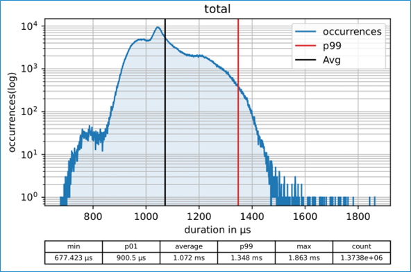
Fig. 29 Histogram of the robot cycle time. The 2 ms limit was maintained throughout the entire test.