
2. Getting Started
This section will assist you in the initial setup of voraus Roboception. Examples like a first bin picking program can be found in Examples. For detailed camera questions while installing and using the Roboception camera, please refer to the Roboception documentation.
2.1. Requirements
Access to the Web GUI of the Roboception controller. Use the rcdiscover tool provided by Roboception to initially connect to the camera. Afterwards configure the network settings according to your needs as described in the network configuration documentation.
A running voraus.core software installation on a UP Squared IPC or a local device, for the installation on a rc_cube please refer to section Installation on a rc_cube.
Additionally, you will need to set up your robot for remote control by the voraus.core. This setup varies for different robot manufacturers. Please follow the instructions of the corresponding robot specific setup guide that you received together with this documentation.
2.2. Installation
For an already running voraus.core, it is only necessary to apply the changes to the Docker Compose file as described in section Docker stack configuration. If you want to use a Roboception controller, please refer to section Installation on a rc_cube.
2.2.1. Docker stack configuration
If the voraus.core is already installed and running on a recommended UP Squared IPC or on your local device, the voraus Roboception can be activated directly. To do this, add the following to the Docker compose file:
environment:
    ...
    VORAUS__components__voraus-roboception-app__enabled: True
    ...
ports:
    ...
    - 5000:5000 # voraus-roboception-app
    ...
restart: unless-stopped
...
labels:
    - com.roboception.app.http.port=8080
The unless-stopped under restart makes sure that if the rc_cube is restarted, the software stack is as well.
Note
The default port of the voraus Roboception is 5000. It cannot be adjusted.
2.2.2. Installation on a rc_cube
Instead of running the voraus.core on a UP Squared IPC or a local device, it can also run on several Roboception controllers that come with the UserSpace feature. The list of Roboception controllers includes, but is not limited to:
rc_cube I Industrial Edge Computer
rc_cube S Edge Computer
You should already have access to the Web GUI of the Roboception controller. Use the rcdiscover tool provided by Roboception to initially connect to the camera and afterwards configure the network settings according to your needs. For further information on how to get access to the Web GUI, please refer to Roboception’s documentation.
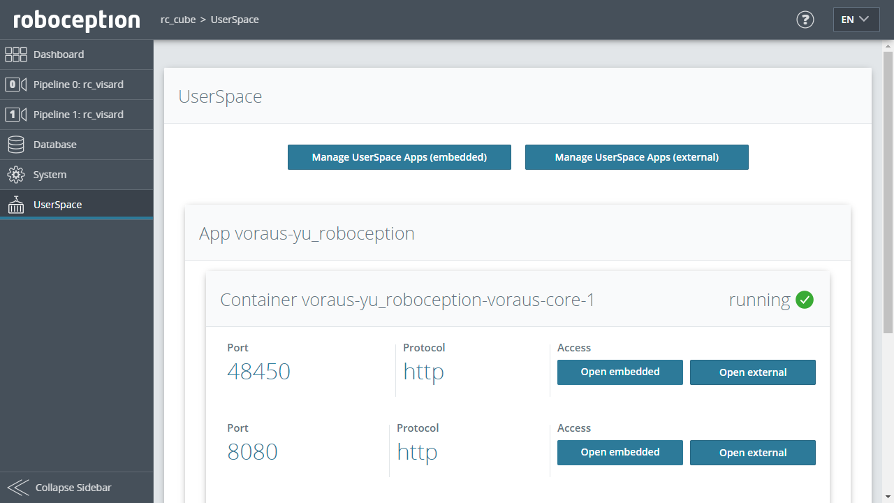
Open the Roboception Web GUI in your browser and navigate to the UserSpace section. The underlying Portainer UI can be accessed by clicking the Manage UserSpace Apps button. From here, please create your needed Docker compose file and include the additions from section Docker stack configuration.
Note
To run the voraus.core on the rc_cube, a license dongle is needed in order to run the voraus software.
Open the voraus.operator on an rc_cube
Once the voraus.core is configured inside the rc_cube’s Portainer UI, you can access the voraus.operator by navigating
to the UserSpace section and clicking either on the Open embedded or Open external button of the
voraus.core app, like shown in (roboception_userspace).
Opening the Portainer UI in an external window is not possible, if the Web GUI is accessed directly via a monitor connected to the Roboception device.
2.3. Configuration
After installation, some configurations are required to make full use of the voraus Roboception.
2.3.1. Configuring the Roboception settings
The voraus.operator provides a few basic settings for the communication to the Roboception controller, that have to be configured as follows. In the voraus.operator, open the settings page and click on the ROBOCEPTION (Fig. 3/(1)) panel. Set the Roboception API endpoint to the url that you use to open the Roboception Web GUI in your browser (Fig. 3/(2)). Do not forget to define the network protocol like http:// or https://. An example of a valid Roboception API endpoint is http://192.168.1.1/. Afterwards, an available Streaming mode can be selected (Fig. 3/(3)).
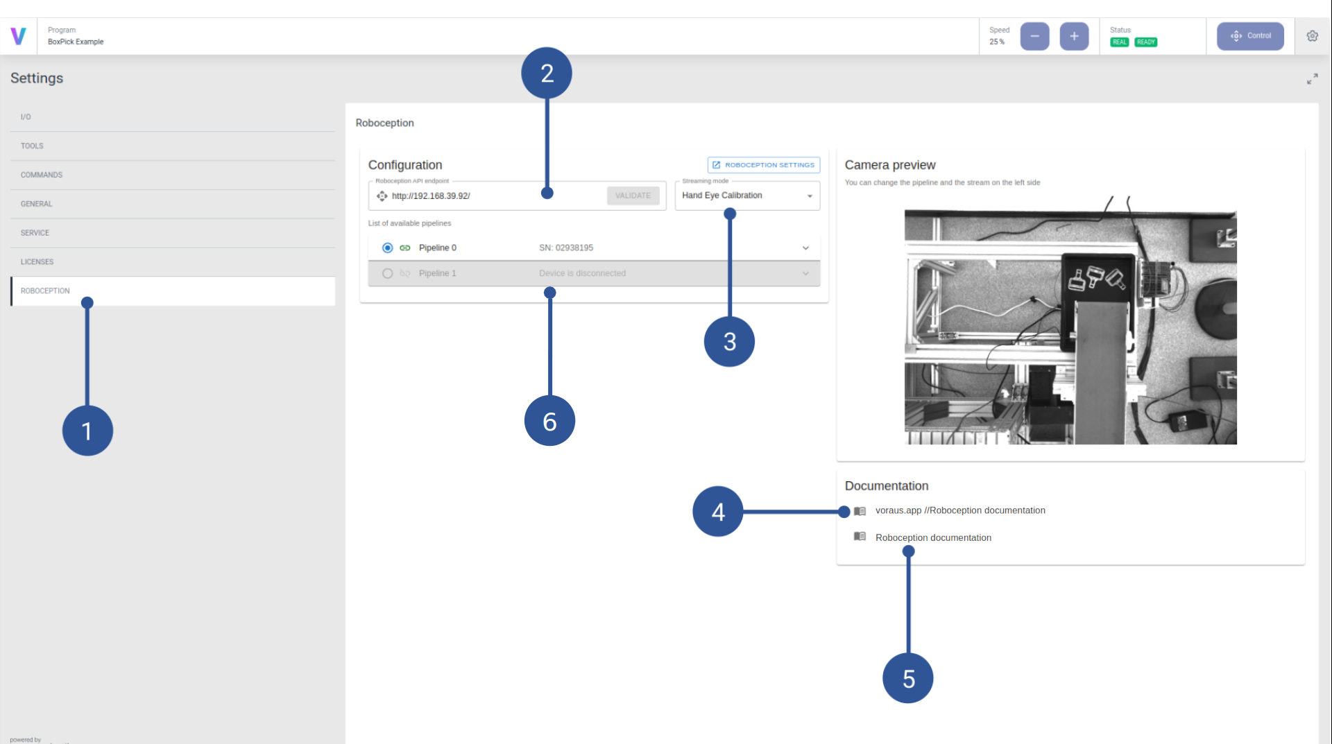
If you are using an rc_cube, the list of available pipelines is also displayed (Fig. 3/(6)).
Note
This is just an overview to validate the availability of the pipelines. The configuration of the pipelines has to be done in the Roboception Web GUI.
Additionally, useful documentation links are provided on the settings page. The voraus Roboception documentation (Fig. 3/(4)) links to this document, which contains the Python API documentation of the Roboception app and documentation about the usage of the Roboception commands in the programming interface. The Roboception documentation (Fig. 3/(5)) links to the official Roboception documentation, where useful information about the Roboception features is provided.
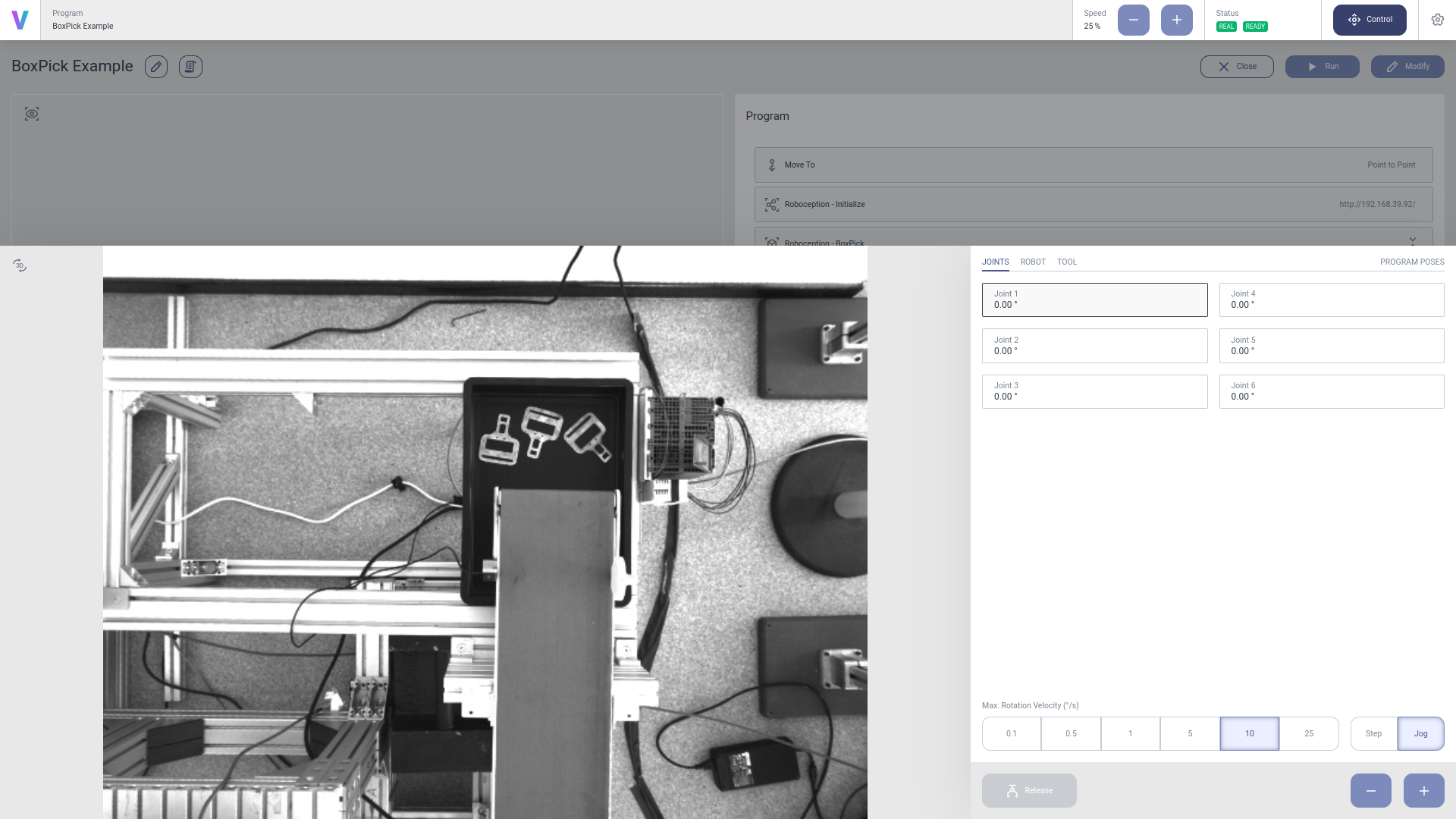
If the connection has been established successfully, the camera preview will update with a live image of the camera. Among other places, the live image is displayed in the control panel (see Fig. 4). This enables you to jog the robot while watching the camera stream at the same time. Only a single camera stream can be available at a time. It is selected by the Pipeline (Fig. 3/(6)) from which the stream is selected from and the Streaming mode (Fig. 3/(3)), that can toggle between the available streams of the pipeline (Left camera, Right camera, Hand-Eye Calibration, …).
2.3.2. Configuring the Roboception database and detection modules
The essential part of a bin picking program is the detection of objects. For this to work, the detection task has to be configured. The detailed configuration and optimization is done in the Roboception Web GUI and in the voraus.operator you will only have to reproduce the detection requests. This section will guide you through the configuration steps that have to be taken inside the Roboception Web GUI. For a detailed documentation of the features described in this chapter, please read the official Roboception documentation
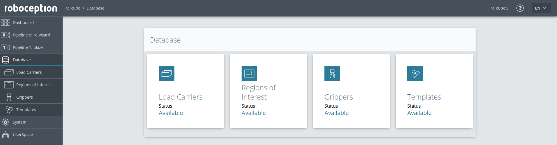
In the database module (Fig. 5) of the Roboception Web GUI, add and define the tool you want to use.
If a region of interest is required to limit the area of valid detections, define one in the Region Of Interest database module.
In case you want use the CADMatch or the SilhouetteMatch detection modules, define and configure the templates in the Templates database module.
Optionally define the box you will be using inside the Load Carriers database module.
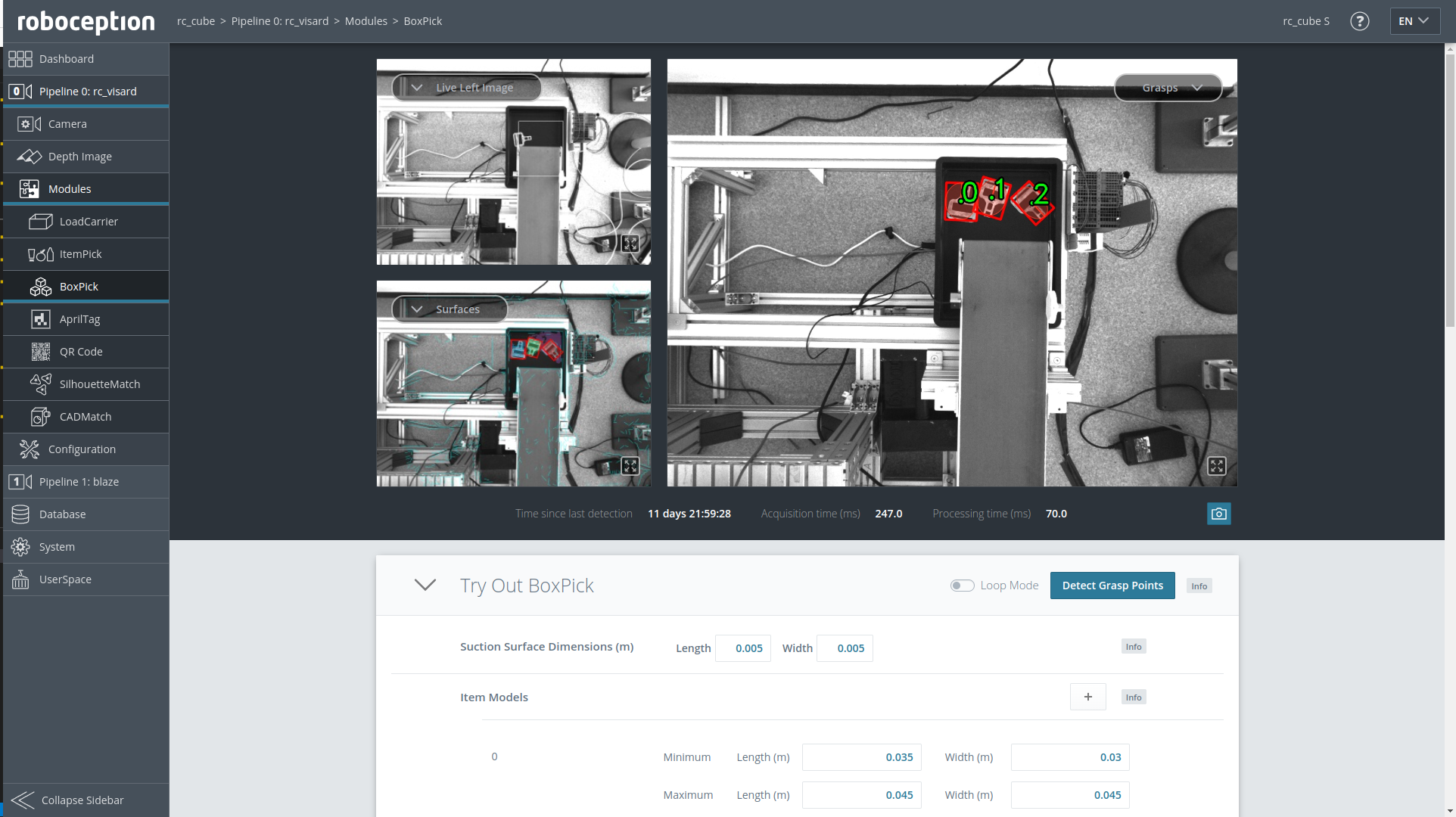
Decide which detection module of the Roboception features fits best for your use case. Open the corresponding module in the Roboception’s Web GUI and configure the detection command. Try out your detection in the Web GUI to see if the choosen configuration is valid (Fig. 6).
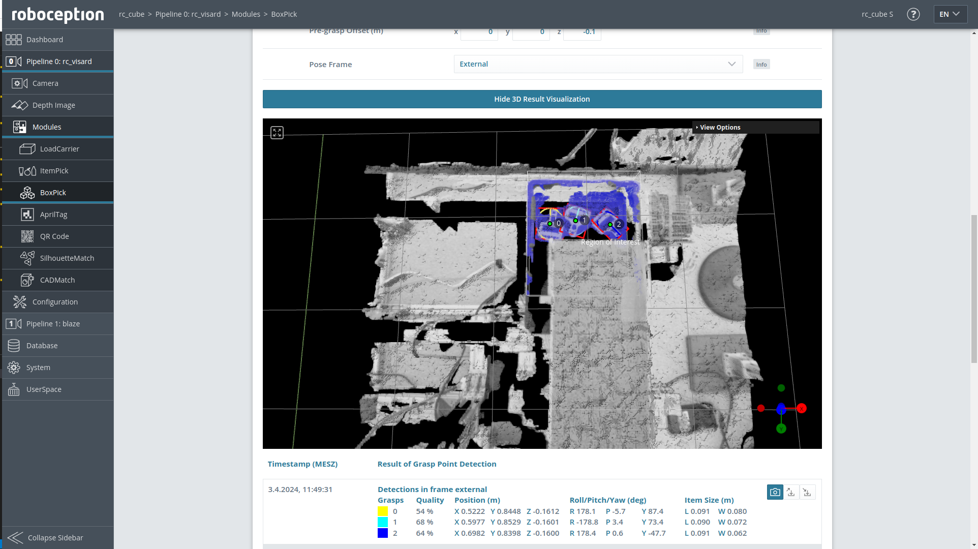
You also might want to check the results in the 3D Result Visualization (Fig. 7).
2.3.3. Hand-Eye Calibration of the camera
Note
For the Hand-Eye Calibration it is recommended to set the Streaming Mode to Hand-eye calibration on the Settings page. That way the live camera preview will automatically display the detected calibration grid if it is visible.
The voraus.core needs to know the spatial relation of the camera to the robot. Each time the camera is displaced a Hand-Eye Calibration has to be executed. The voraus.core provides a simple way of running the Hand-Eye Calibration without any effort.
Note
Currently, only statically mounted cameras are supported. Robot mounted cameras will be added soon.
Mount a calibration grid to the robot’s end-effector. Ensure that the grid is mounted properly. It must not move or swing during the robot’s movement.
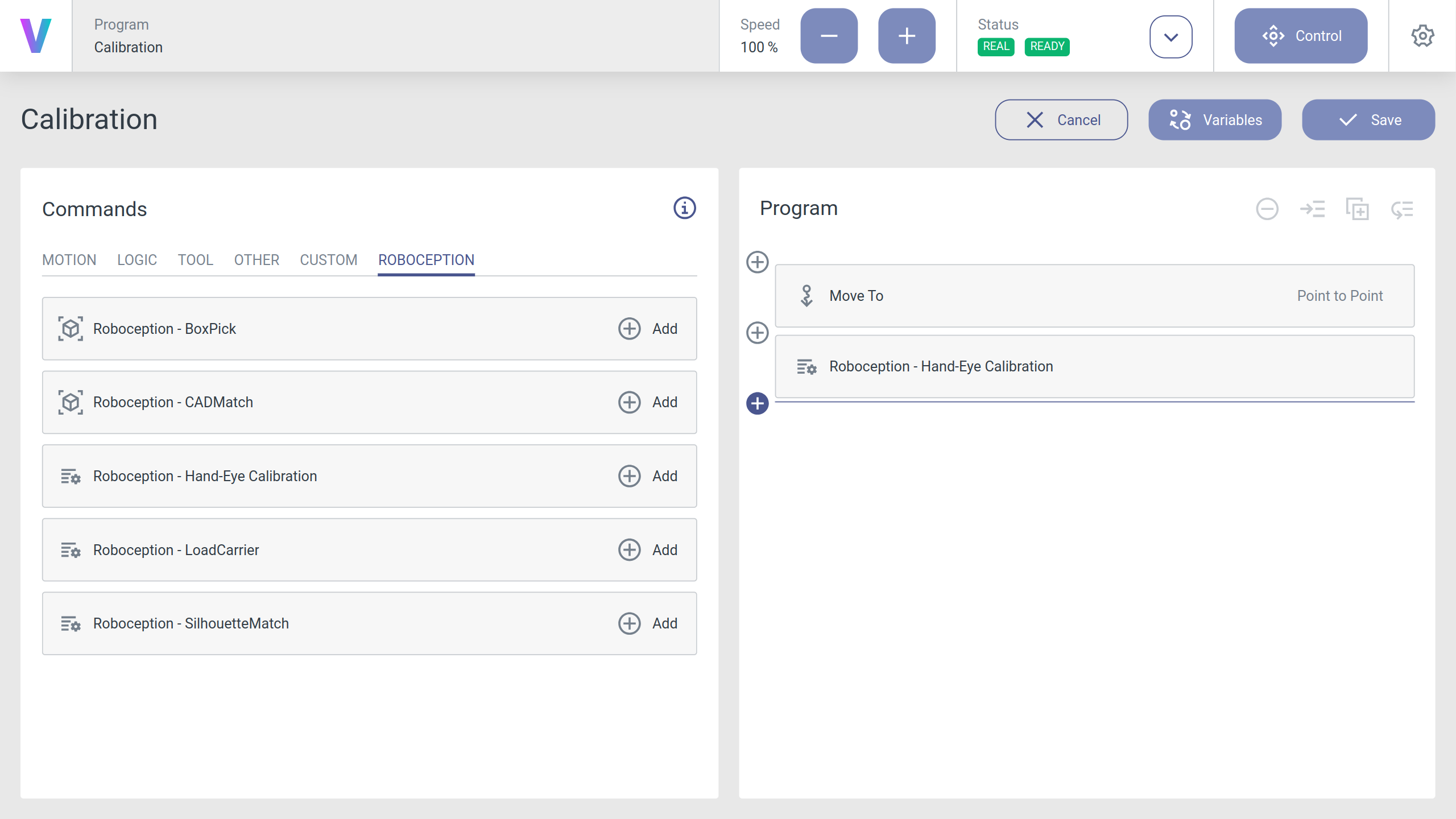
Create a new program with a Roboception - Hand-Eye Calibration command (see Fig. 8).
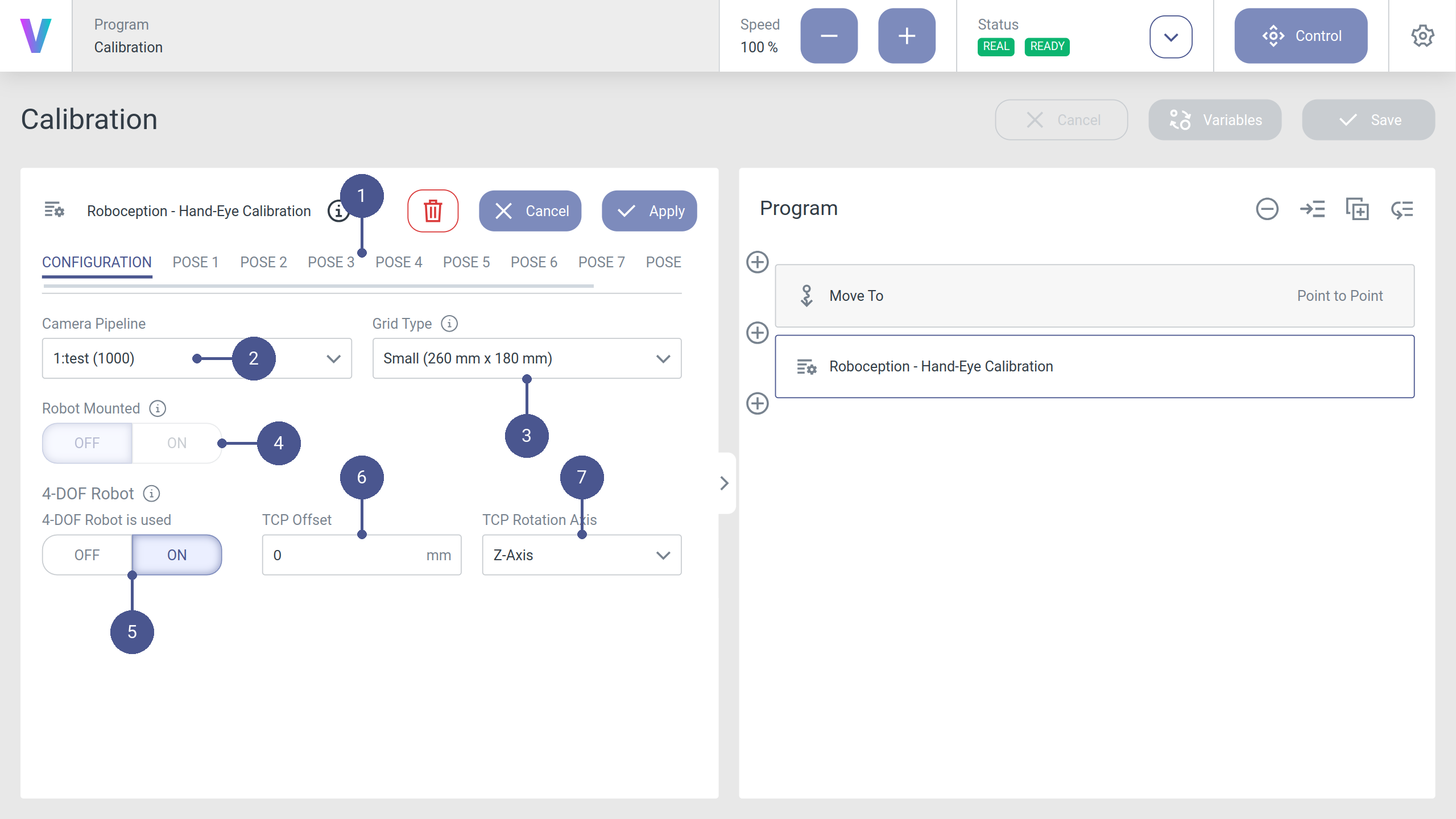
In the CONFIGURATION tab of the command (Fig. 9/➊), configure the Camera Pipeline (Fig. 9/➋) of the camera you want to calibrate and the Grid Type (Fig. 9/➌) of your calibration grid (available for purchase at Roboception).
Note
For a detailed overview of every configuration option, please refer to Roboception - Hand-Eye Calibration.
Note
For robots with only 4 degrees of freedom (4DOF) (Fig. 9/➎) you have to provide additional information about your setup (Fig. 9/➏ and Fig. 9/➐). View the Roboception documentation’s Hand-Eye Calibration chapter and/or Roboception - Hand-Eye Calibration for more details.
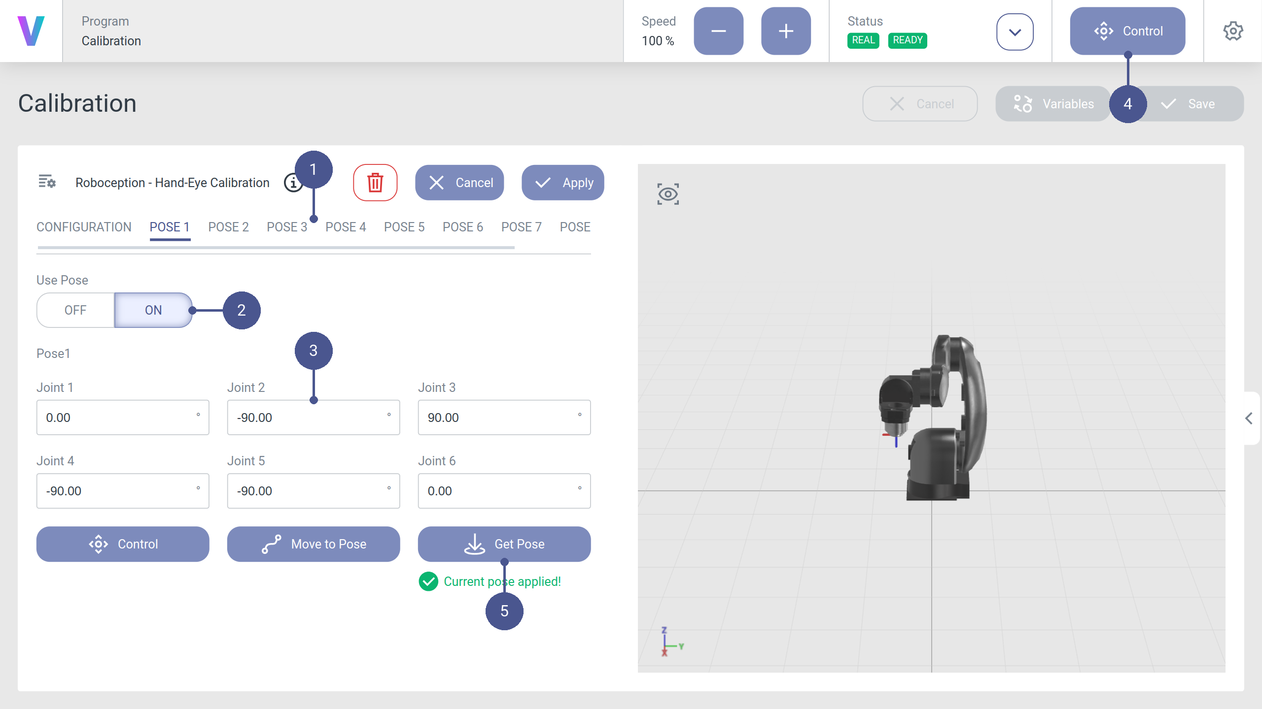
Now configure the robot poses that will be used to calculate the camera transformation. For each pose, open the corresponding pose tab (Fig. 10/➊), navigate to the Control Panel (Fig. 10/➍) and move the robot to the desired pose. For an example of recommended poses, please see the Hand-Eye calibration chapter in the Roboception documentation. When the desired pose is reached, apply the pose in the pose tab by clicking Get Pose (Fig. 10/➎). At least four poses are required, but more are recommended.
Warning
The robot will move directly from one pose to the next one. Make sure that no collisions can occur, especially with the grid.
Once the poses are defined, save the program and start it. The robot will move to the defined poses and calculate a Hand-Eye transformation. The results will be logged to the program log. Review the results and rerun the calibration with adjusted poses if the calibration quality does not fulfill your requirements.
Keep the program and do not delete it since you might want recalibrate the camera at a later time.
Note
If the grid is not visible at one of the defined poses, an error will be raised with the corresponding pose index. In this case, configure the pose, move the robot to the stored position and either adjust the pose if the grid is not visible or adjust the camera parameters if the brightness of the image is insufficient.
Now you have configured all the necessary settings, and you are ready for your first application. In the chapter Examples your will find further tutorials and examples.