2. voraus.operator
To open the voraus.operator, please open a browser, it is recommended to use Chrome. If you use the default configuration, please type in the following IP address: https://192.168.1.1:8080
2.1. Safety during operation
Warning
Improper usage of the software can cause injury and property damage.
Before using the robot software, perform a safety assessment according to the current standards (machinery directive, robot norm, etc.).
Carry out all operating steps according to the information and notes in this manual.
- Note the following before moving the robot via software:
Ensure that the robot is mounted securely.
Ensure that no unauthorized persons are in the working and danger area of the robot.
Ensure that the defined roles are consistent with the companies personnel.
Ensure that the owner has been informed about the functionality and risks of the application.
2.2. User interface overview
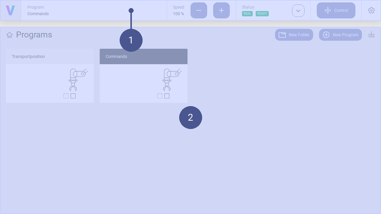
Fig. 14 User interface structure
➊ Navigation bar ➋ Work window
The user interface consists of the navigation bar (Fig. 14/➊) and the work window (Fig. 14/➋). The work window and its content change dynamically. Exemplary, the home screen is shown in the work window providing a quick access to applications.
In addition to the creation and management of programs, this includes manually moving of the robot and setting of the robot parameters. The navigation bar is displayed in every screen and contains the following basic commands in addition to the status message of the robot:
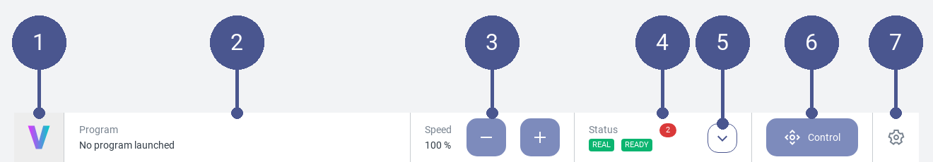
Fig. 15 Navigation bar
Fig. 15/➊ |
Logo - Return to the home screen |
Fig. 15/➋ |
Program - Displays the active program. Click to open it. |
Fig. 15/➌ |
Speed - Adapt the speed of the robot. The maximum value of 100 % the upper limit set in the settings / commands. |
Fig. 15/➍ |
Status - Displays the status of the robot. Clicking the button opens the status corresponds to menu. |
Fig. 15/➎ |
Status Quick Access - Opens the quick access menu for the operation of the robot. |
Fig. 15/➏ |
Control - Opens the manual control menu. |
Fig. 15/➐ |
Settings - Opens the settings menu. In this menu, the parameters of the robot can be set. |
2.2.1. General Settings
In the general settings, personal adjustments can be made, such as selecting the language and system specific information are provided. Use the following steps to navigate to the general settings page:
Click on the Settings Icon to open the settings page.
Click General in the settings menu.
Language
The language can be changed with opening the dropdown menu and selecting the desired language. Supported languages are English, German, Chinese, Japanese.
Drag & Dop
Activate or deactivate the function to drag & drop commands
Software Version
See the latest software version
2.3. Operating the robot
2.3.1. Manage programs
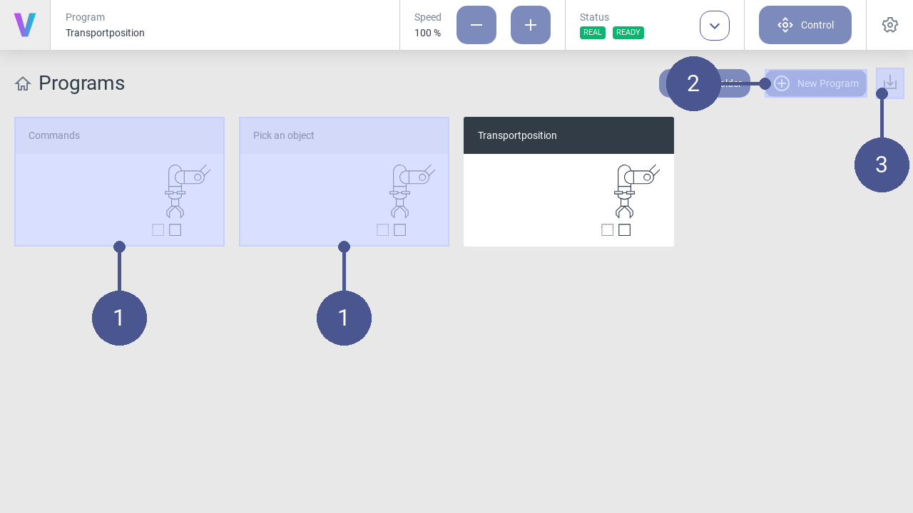
Fig. 16 Home screen
Programs (Fig. 16/➊) are displayed on the home screen of the user interface.
A new program can be created via the New Program button (Fig. 16/➋). Programs can be imported via the Import Program button (Fig. 16/➌).
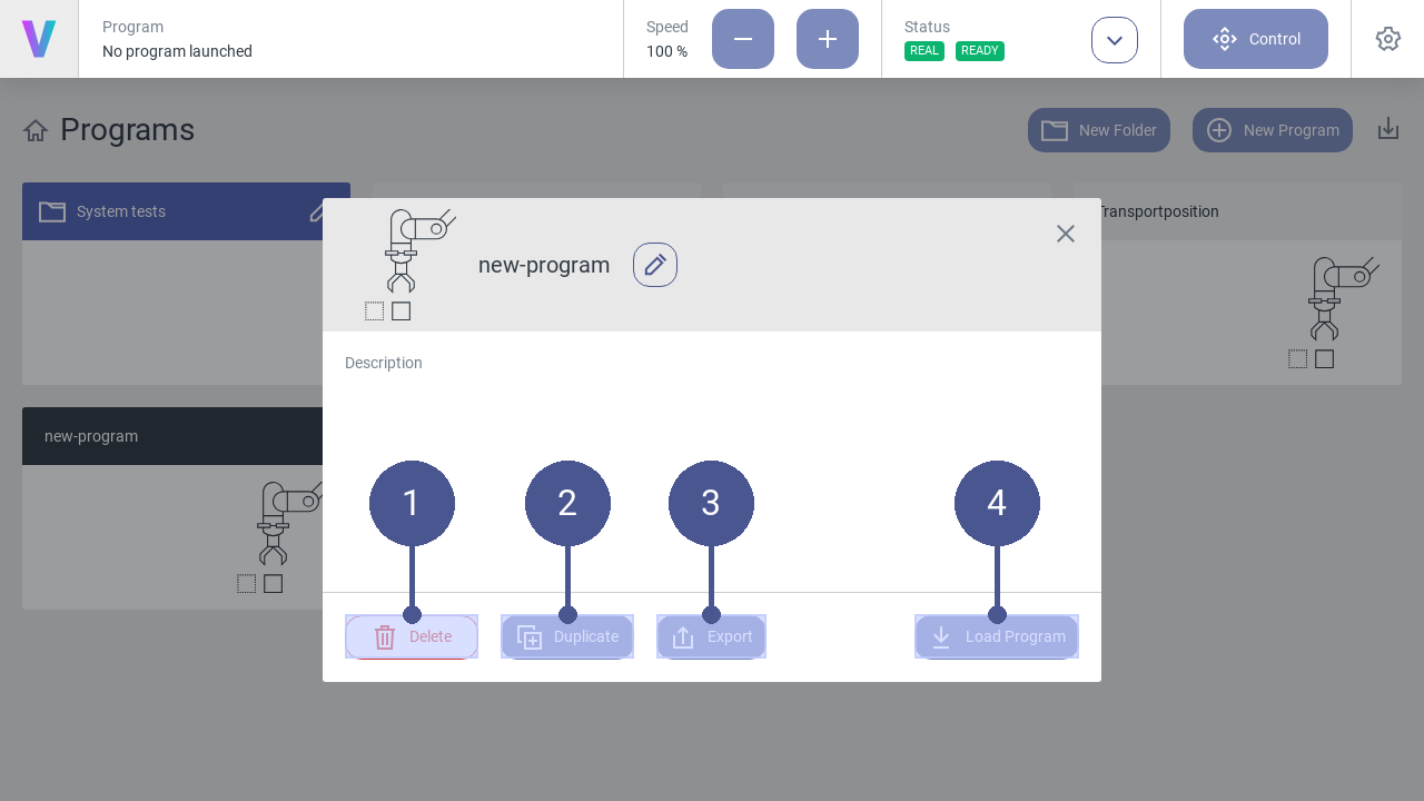
Fig. 17 Manage programs
To manage existing programs, click on the desired program on the main screen.
Note
The menu (Fig. 17) opens.
Click on one of the following buttons:
Fig. 17/➋ |
Delete - Delete the selected program. |
Fig. 17/➋ |
Duplicate - Copy the selected program. |
Fig. 17/➌ |
Export - Export the selected program. |
Fig. 17/➍ |
Load Program - Load the selected program. |
Folders
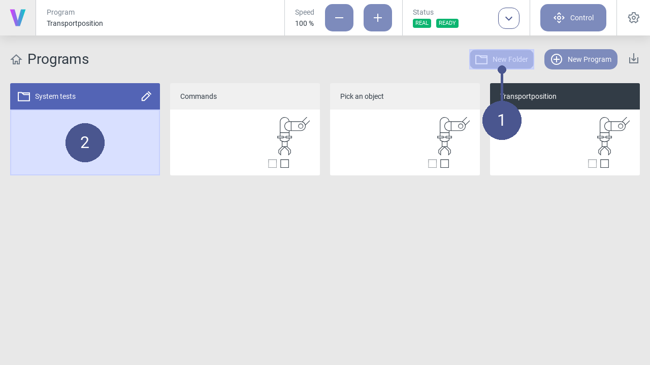
Fig. 18 Manage folders
Folders can be created on the home screen in addition to programs. They are useful for grouping and sorting programs.
To create a new folder:
Press the New Folder button (Fig. 18/➊).
Enter a meaningful name.
Press the save icon.
Programs can be moved to folders (Fig. 18/➋) via drag and drop. To move a program out of a folder, it must be dragged and dropped onto the navigation title Programs.
It is possible to rename and delete folders by clicking the edit icon. Please note deleting a folder deletes all included programs too. This cannot be undo. Folder cannot be deleted when an included program is currently loaded.
2.3.2. Use simulation mode
In simulation mode, robot movements are simulated in the user interface, based on a virtual robot model. The real robot does not perform any movements in simulation mode.
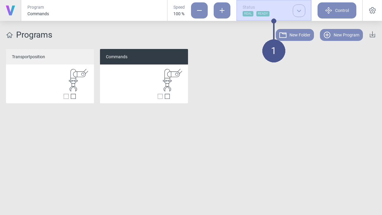
Fig. 19 Status
Click on the Status button on the home screen (Fig. 19/➊).
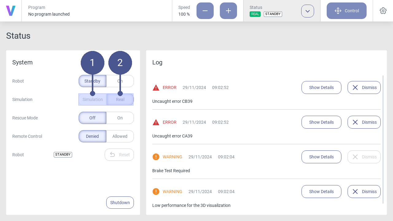
Fig. 20 Activate/Disable simulation mode
To activate the simulation mode, click on the Simulation button in the status menu. (Fig. 20/➊).
The simulation mode is activated.
All robot movements (e.g. when executing programs or when moving manually) are now displayed exclusively virtually based on the robot model in the user interface.
3. To deactivate the simulation mode, click on the Real button in the status menu. (Fig. 20/➋).
2.3.3. Configure Tool
Fig. 21 Home screen
Click on the Status button on the home screen (Fig. 21/➊).
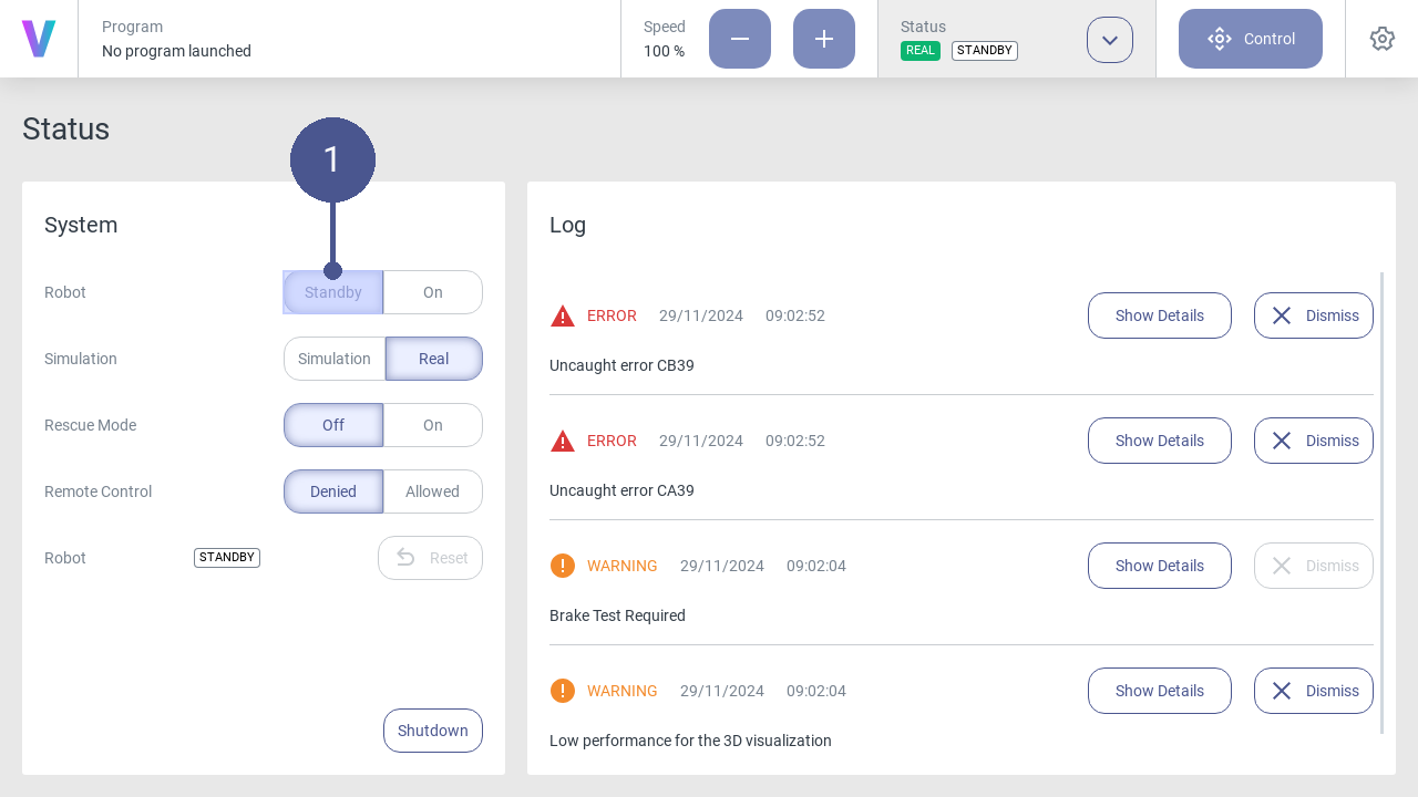
Fig. 22 Robot in standby mode
Click Standby in the status menu. (Fig. 22/➊)
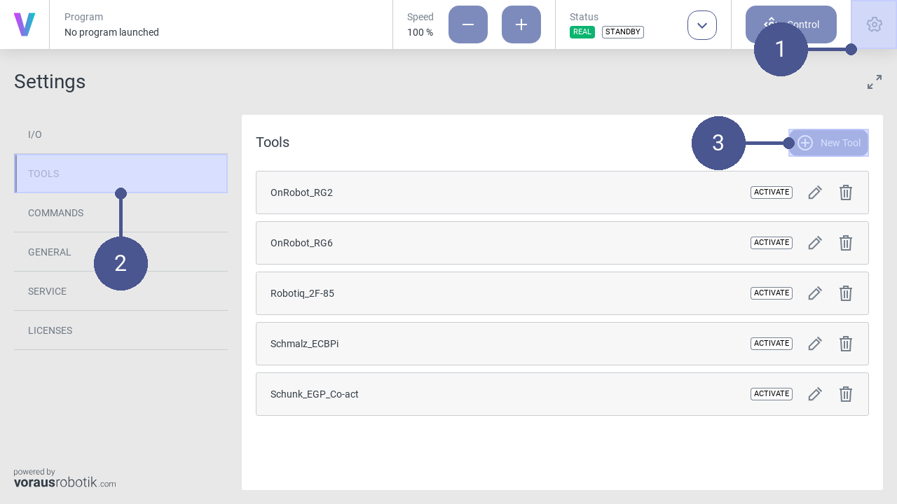
Fig. 23 Open the settings menu
Click the settings icon in the navigation bar (Fig. 23/➊), to open the settings menu.
In the settings menu, click on TOOLS in the left tab to open the window of the tool’s settings (Fig. 23/➋).
Click on New Tool (Fig. 23/➌).
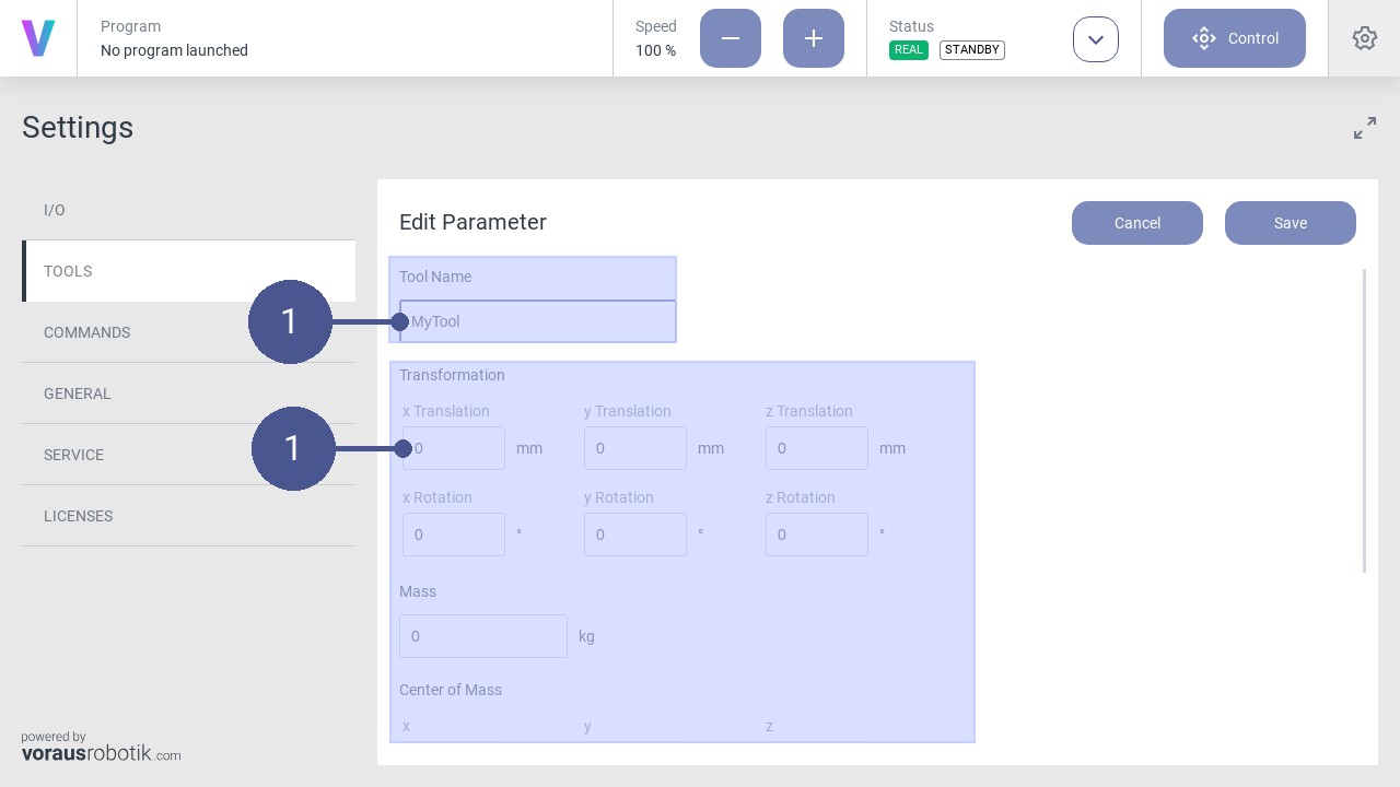
Fig. 24 Set tool parameters
Name the tool and enter its parameters (Fig. 24/➊).
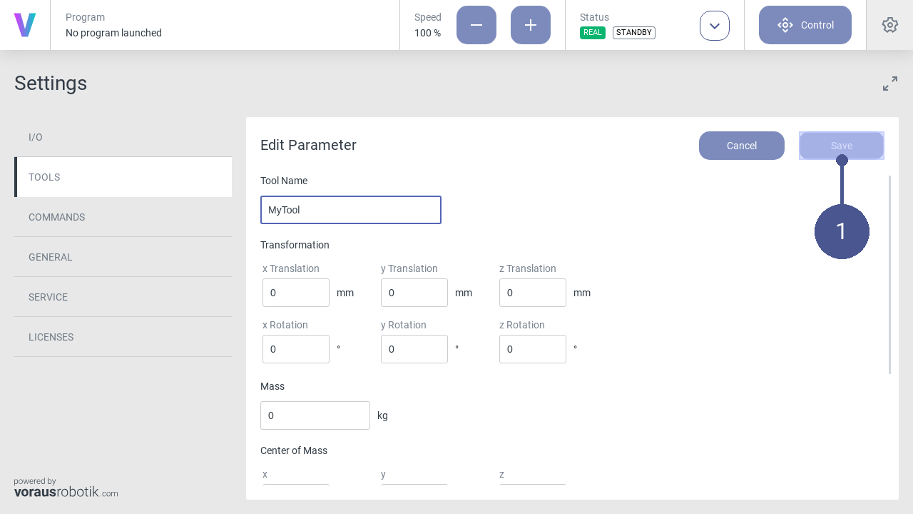
Fig. 25 Save tool parameters
Click Save to save the tool parameters (Fig. 25/➊).
2.3.4. Create a new program
Personnel: System integrator
Requirements
The safety configuration for the new program has been correctly parameterized by the system integrator.
The robot is in manual operating mode.
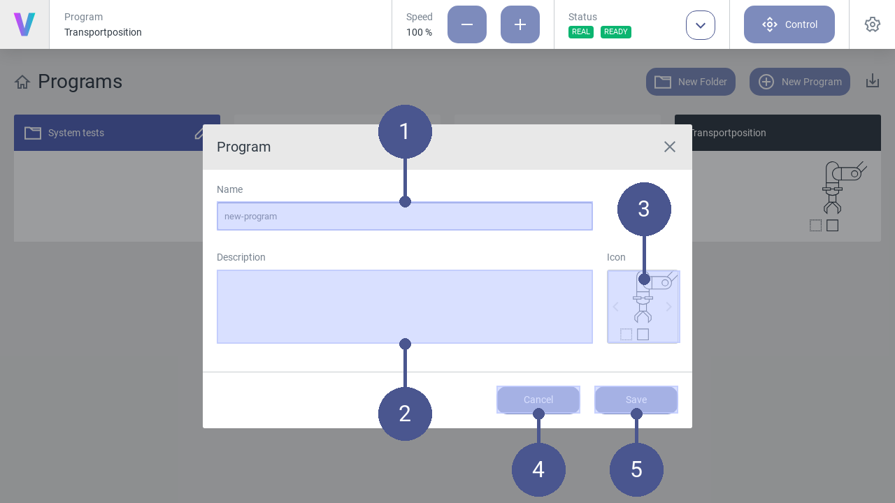
Fig. 26 Create new program
To create a new program, click New Program on the main screen. The menu (Fig. 26) opens.
Enter Name and Description of the program function (Fig. 26/➊ + ➋).
Select an appropriate Icon by using the arrows (Fig. 26/➌).
Click Save to create the program (Fig. 26/➎). Otherwise click Cancel to return to the main screen (Fig. 26/➍).

Fig. 27 Add commands to program
5. In the program menu (right half of the screen), define the program sequence by inserting individual command blocks (Fig. 27).
To do so, proceed as follows:
6. In the tab select the required command category by clicking on it (Fig. 27/➊). The following command categories are available:
MOTION
Define movement patterns of the robot.
LOGIC
Select logic commands such as repeat, to execute a group of commands in a loop.
OTHER
Create a group of commands to improve the program´s readability.
CUSTOM
Apply your individual commands.
Select the desired command block (Fig. 27/➋) and add it to the program sequence by clicking on the plus symbol (Fig. 27/➌) The new command block is added to the program flow at the position of the colored cursor (Fig. 27/➍).
After assigning all the required command blocks, Save your final program and enjoy its impact (Fig. 27/➎).
The newly created program can be loaded and executed by the operator on the main screen.
2.3.5. Load and execute programs
Personnel: Operator
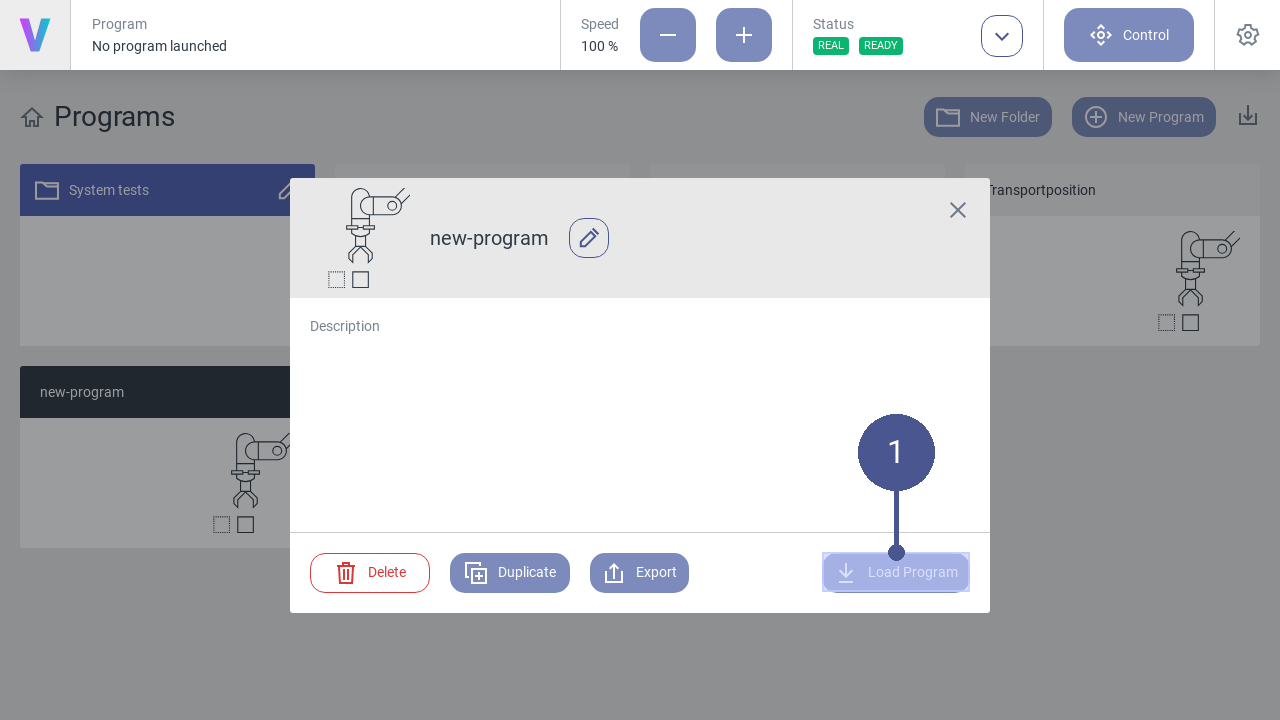
Fig. 28 Load program
To load a program, click on the button of the desired program on the home screen.
Note
The pop-up (Fig. 28) opens.
2. Click the Load Program button to open the selected program (Fig. 28/➊).
In the program menu (Fig. 29), the program sequence is displayed as a sequence of the individual command blocks (Fig. 29/➋).
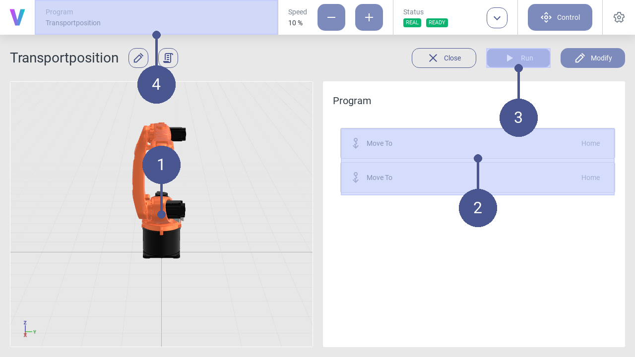
Fig. 29 Start program
To start the program, click Run (Fig. 29/➌).
The robot executes the program according to the sequence of the command blocks.
Note
Virtual robot
In the left menu section, the movements are displayed using a virtual robot model (Fig. 29/➊). In the navigation bar, the currently loaded program is displayed at any time (Fig. 29/➍).
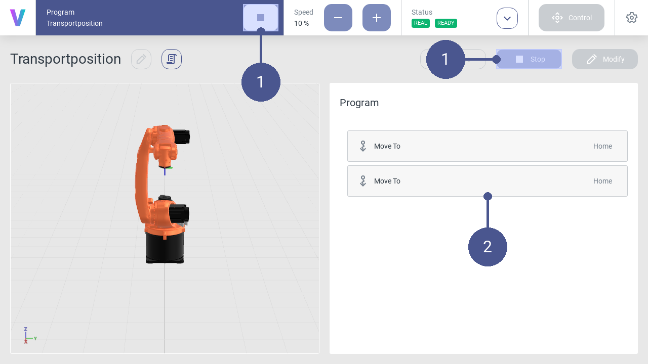
Fig. 30 Stop program
To stop the program, click the Stop button in the navigation bar or the program menu (Fig. 30/➊).
Note
Program sequence
The currently executed command sequence is displayed via a colored time bar (Fig. 30/➋).
2.3.6. Edit program
Personnel: System integrator
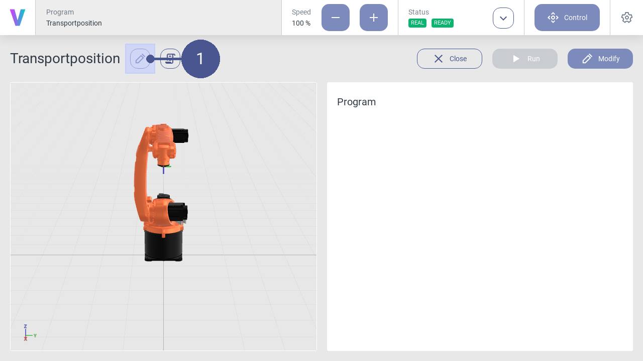
Fig. 31 Edit program
To edit a program, click on the pencil icon next to the program name (Fig. 31/➊).
Enter a new name or change the program description if needed.
Note
The pop-up menu opens (Fig. 32).
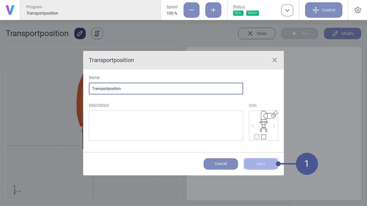
Fig. 32 Save program changes
Click Save to save the changes (Fig. 32/➊).
Note
The program can also be edited by clicking on the icon next to the program name in the pop-up window within the home screen.
2.3.7. Move robot manually
Warning
Risk of injury due to manual movement of the robot!
When moving the robot manually, there is a possibility that the robot is moved in an unsafe environment without prior risk assessment. In the event of physical contact, injuries may occur due to improper manual operation of the robot.
Ensure that the robot is only moved manually by the responsible system integrator.
Ensure that no unauthorized persons are in the working and danger area of the robot.
Ensure that no pointed or sharp-edged tools or devices are mounted to the robot.
Personnel: System integrator
Requirements
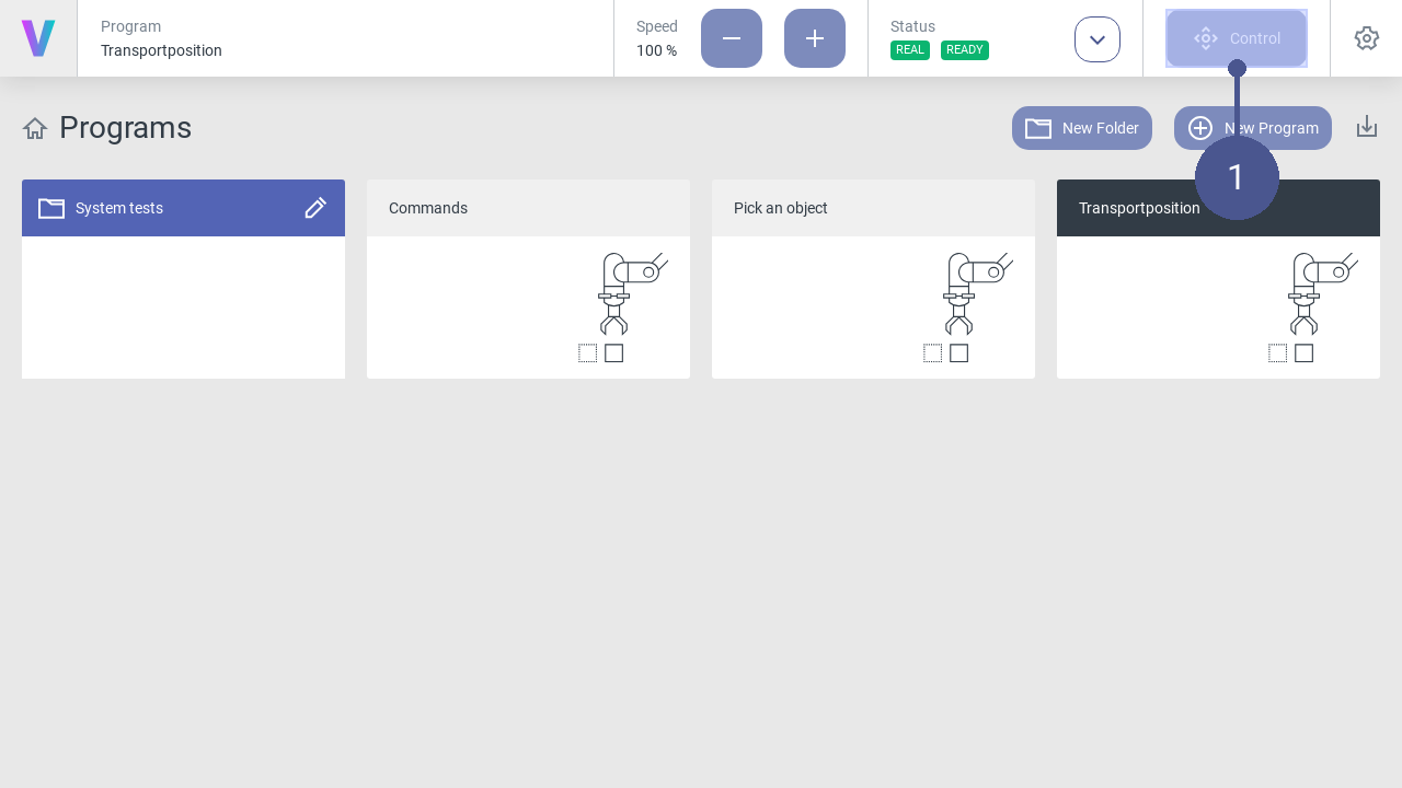
Fig. 33 Open control panel
Click Control in the navigation bar (Fig. 33/➊).
Note
The control menu opens (Fig. 34).
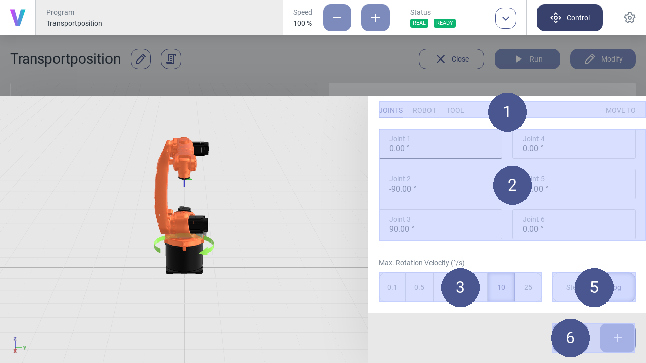
Fig. 34 Control panel
Select the desired coordinate system from the tabs (Fig. 34/➊).
Select the axis for which a movement is to be executed (Fig. 34/➋).
Select the jogging method (Fig. 34/➎):
- Step (Step-Jogging)
The robot moves step by step along the selected axis.
- Jog (Jogging)
The robot moves continuously along the selected axis.
Select angle length and angular velocity (Fig. 34/➌).
Click the plus or minus button to move the robot forward or backward along the selected axis (Fig. 34/➏).
Note
Move robot
Press and hold the plus or minus button to move the robot in a continuous motion while jogging.
Move robot to input pose
The robot can be manually moved to a specific target pose. Therefor, the target pose needs to be entered into the input fields.
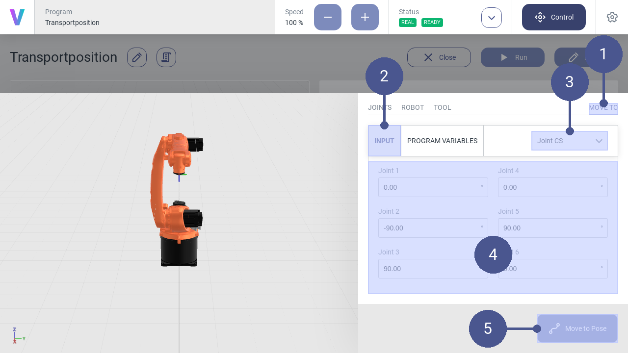
Fig. 35 Input pose
Open the control panel.
Navigate to MOVE TO (Fig. 35/➊) and select INPUT (Fig. 35/➋).
Select the coordinate system of the target pose (Fig. 35/➌).
Enter the target pose in the input fields (Fig. 35/➍).
Press and hold the Move to Pose button until the target pose is reached (Fig. 35/➎).
The robot is now at the target pose.
Move robot to program variable
The robot can be manually moved to a specific program pose variable. Therefor, the program variable needs to be selected first.
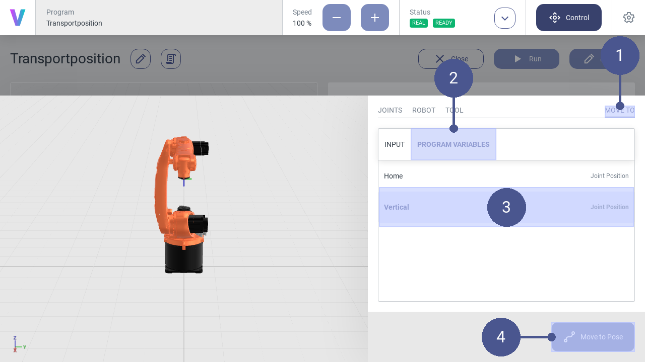
Fig. 36 Program variables
2.3.8. Reset system after software failure
The following section describes how to restart the robot after an emergency stop or after a change of the operating state.
Reset software failures.
Personnel: Operator
A software error can, for example, be triggered by system errors or incorrect movement of the robot.
When a system error is triggered, a notification appears in the status bar (Fig. 37/➊) and the error message is displayed in the notification bar (Fig. 37/➋).
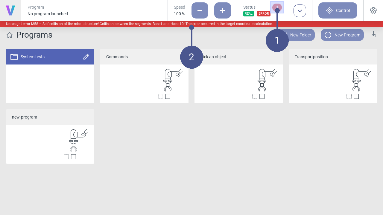
Fig. 37 Note error message
Open the status page and view details of the error message in the log (Fig. 38/➊).
Click Reset (Fig. 38/➋). The robot is set back to the Standby status (Fig. 38/➌). This can take a few seconds.
The robot can then be switched on again (Fig. 38/➍).
Other errors may be triggered during the process. In this case, follow the instructions in the log.
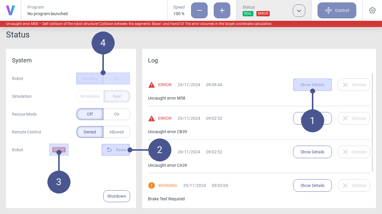
Fig. 38 Reset errors
2.3.9. Create a Move to command
Personnel: System integrator
Requirements
A new program has been created.
After creating a new program, the program editor opens automatically. Logic can be added to the program by adding individual commands via drag and drop or by clicking.
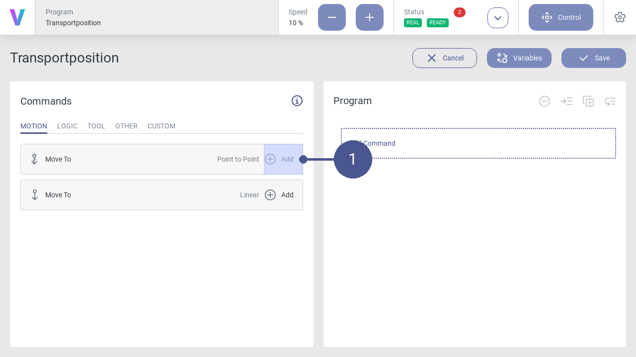
Fig. 39 Add command
Click the Add button of the Move to - Point to Point command in the program menu to open the window for a new motion command (Fig. 39/➊).
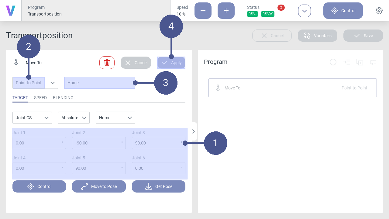
Fig. 40 Move-To command: Home position
Parameterize the motion command for the home position according to the values (Fig. 40/➊).
Make sure that the Point to Point entry is selected in the drop-down list (Fig. 40/➋). Individual adjustments are possible in the tabs.
Enter the name of the motion command (e.g. Home) (Fig. 40/➌).
Save the command with Apply (Fig. 40/➍).
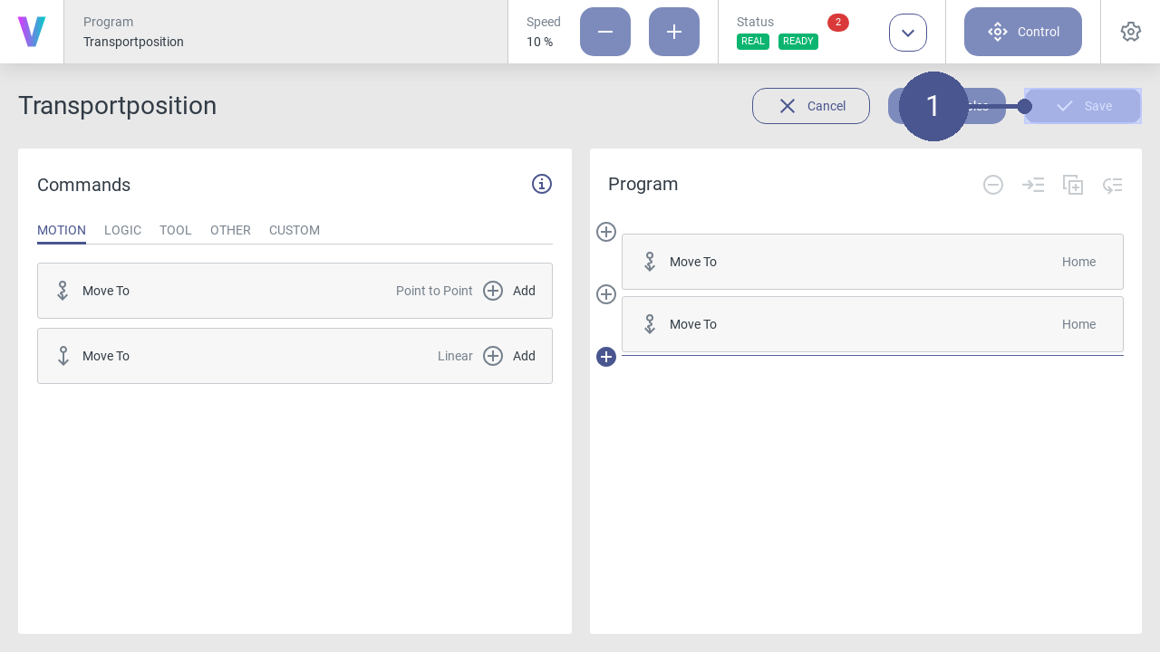
Fig. 41 Save program
When your program is final, click on the Save button (Fig. 41/➊).
The new program can be loaded and executed in the overview screen. Before running your program on a real robot, it’s possible to simulate your path with the digital twin first. To check and switch the mode, have a look on the status screen. While running the program a digital twin of the robot is shown.
Create variable of robot pose
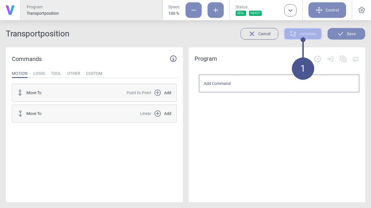
Fig. 42 Open variable manager
Click the Variables button in the program menu to open the window for managing and creating variables (Fig. 42/➊).
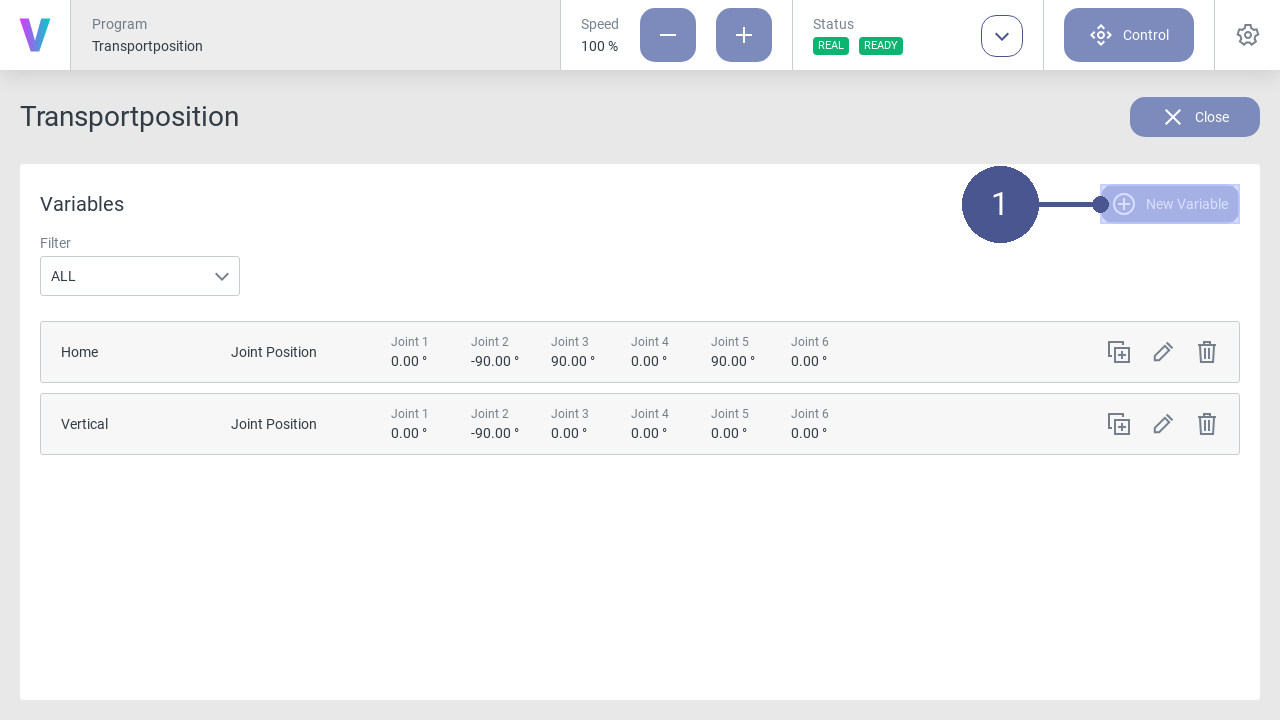
Fig. 43 Variable manager
On the variables page, click the New Variable button to create a new variable (Fig. 43/➊).
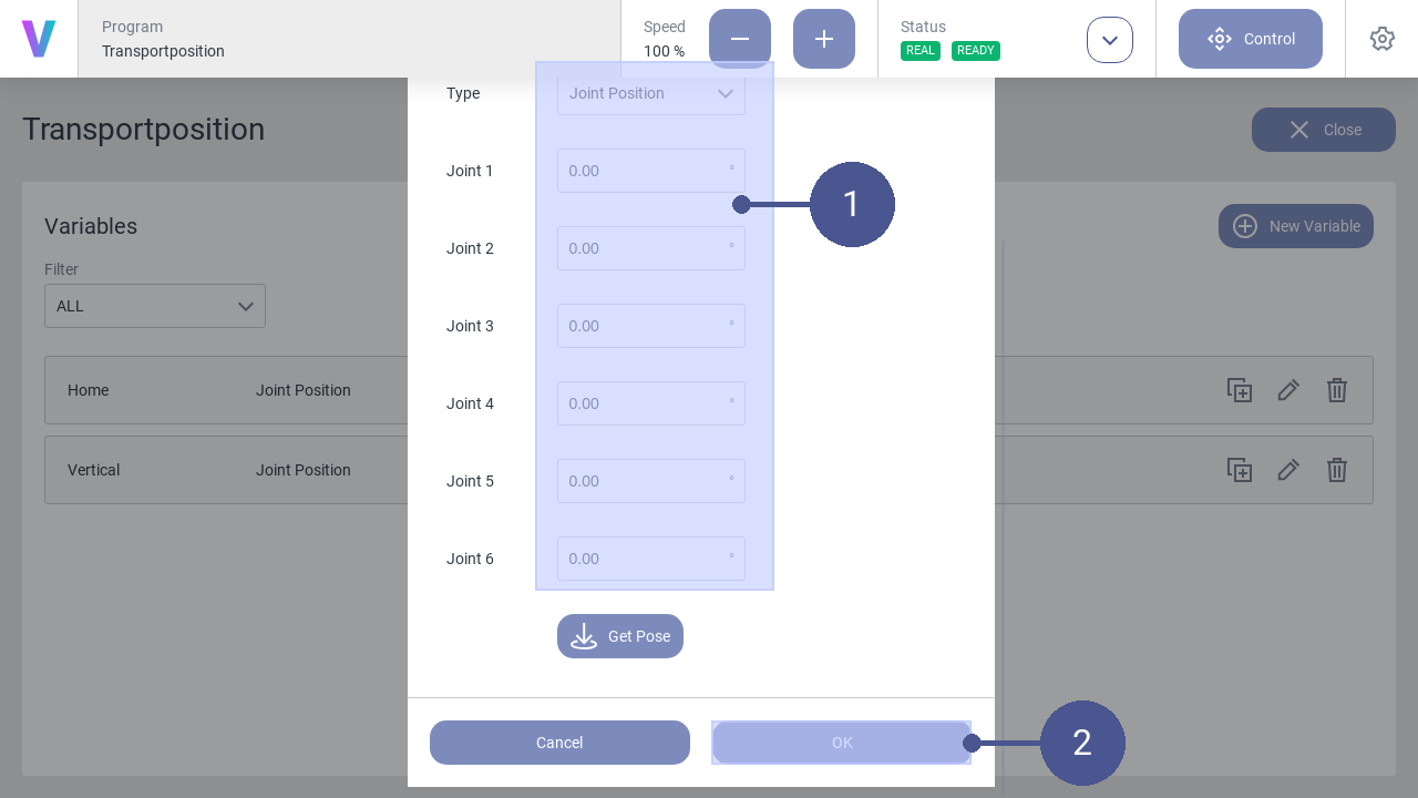
Fig. 44 Create variable
Select the Type Joint Position and parameterize the variable for the position (Fig. 44/➊).
Enter the name of the variable (e.g. Home).
Save the variable with OK (Fig. 44/➋)
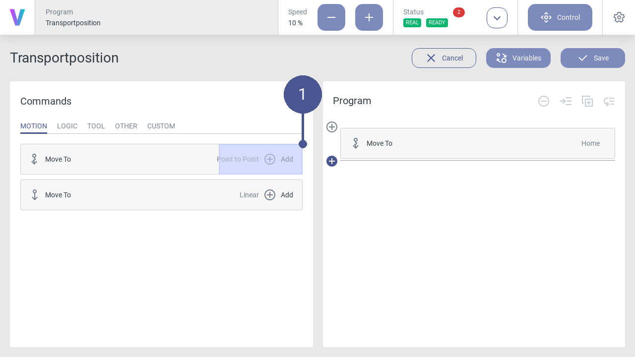
Fig. 45 Create position
Click on the Add button in the program menu to open the window for an additional motion command with the created variable (Fig. 45/➊).
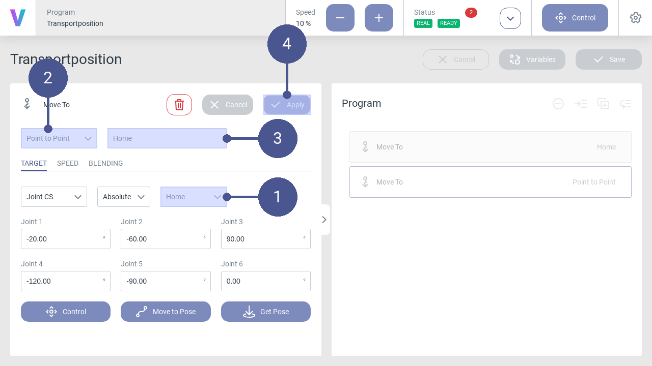
Fig. 46 Add variable
Use the drop-down list to select the variable Home (Fig. 46/➊). Afterwards the coordinates appear in the fields of the axes.
Make sure that the Point to Point entry is selected in the drop-down list (Fig. 46/➋).
Enter the name of the movement command (Fig. 46/➌).
Save movement command with Apply (Fig. 46/➍).
Fig. 47 Save transport position program
Click on the Save button (Fig. 47/➊).
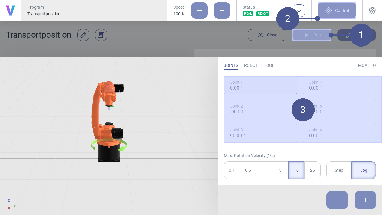
Fig. 48 Check transport position